TVI hints for the v.h.f. man
Low-pass filters and transmitter techniques for use at 50 Mc and up.
Most of the TVI information that has been published to date has been for use on bands below 50 Mc. The ideas presented could be adapted to the v.h.f. man's needs, but there has been little specific information that could be applied directly to transmitters for 50 and 144 Mc. One reason for this is, of course, that a very high percentage of all TVI to date has resulted from operation on 28 and 14 Mc, for it is on these two bands that the harmonic problem is most severe.
We've been primarily concerned with reducing the amount of energy radiated on low-order harmonics of these frequencies, too, so the design techniques have been directed toward harmonics falling in Channels 2 through 6. Even in the case of 28 Mc operation, the lowest harmonic that could cause trouble in the high channels is the seventh, so shielding and filtering methods that cut out the more troublesome low-band harmonics are almost always effective in the high band, too. With v.h.f. operation, however, the problems may be quite different. The 50 Mc operator has a 4th-harmonic possibility in Channels 11, 12 or 13, and tripler stages multiplying to 144 Mc can create quite a rumpus in Channels 9, and 10. Though the amount of TVI thus far resulting from use of the v.h.f. bands is relatively small, there is certain to be more before long as more TV stations begin using the high-band assignments. U.h.f. tv now bursting forth on a commercial scale cannot be expected to make life any easier for the v.h.f. operator.
Sources of v.h.f. tvi
Just as with our lower bands, before we can do anything about reducing v.h.f.-caused TVI we must be sure of the nature of the problem. Unless we know what is causing the interference we will be very lucky if we happen onto a solution. Experience has shown that the principal sources of TVI from v.h.f. rigs are as follows:
- Adjacent-channel interference in Channel 2 from 50 Mc.
- 50 Mc interference on any occupied channel in certain receivers having 45 Mc. i.f.
- Blocking from v.h.f. fundamental frequency, normally only from 50 Mc, and on Channels 2-6.
- Image interference in Channel 2 from 144 Mc, in receivers having 45 Mc. i.f.
- Audio effects similar to BCI.
- Radiation of unwanted harmonics of oscillator or exciter frequencies. Some examples of this are 9th and 7th harmonics of 6 and 8 Mc, respectively, in Channel 2, 10th harmonic of 8.4 Mc oscillators in Channel 6, 3rd harmonic of 25.5 Mc or higher in Channel 3, 7th harmonic of 25 Mc stages in Channel 7, and 4th harmonic of 48 Mc tripiers in Channels 9 or 10. These are just examples; there may be other combinations.
- 4th harmonic of 50-Mc. operating frequency, in Channels 11, 12 or 13.
- Various harmonics of 50 or 144 Mc. falling in the u.h.f. range, Channels 14 through 83.
The first five categories are receiver faults. Nothing can be done at the transmitter to correct the first four items, other than to reduce power or increase the separation between the transmitting and TV receiving antennas. Corrective measures that can be applied to the receiver will be discussed later; what we are concerned with for the present is the transmitter, and steps we can take to reduce its TVI potentiality. Item 5 is a receiver condition, too, but it can be eliminated at the transmitter end by avoiding the use of amplitude modulation. Frequency modulation or c.w. will do the trick ordinarily.
The radiation of unwanted harmonics of-exciter frequencies (Item 6) is a common cause of TVI, particularly where the transmitter is operated in close proximity to TV receivers. In an open layout there is little that can be done to correct this, so the first step is thorough shielding, if the exciter frequencies cannot be shifted to avoid having harmonics in locally-used channels. An example of the latter approach is the avoidance of 8 Mc crystals in 50 Mc work where Channel 6 is used. Crystal or other oscillators in the 8 Mc range may produce sufficient 10th harmonic to interfere in Channel 6, but shifting to a 6 Mc oscillator moves the harmonics to other channels that may not be used locally.
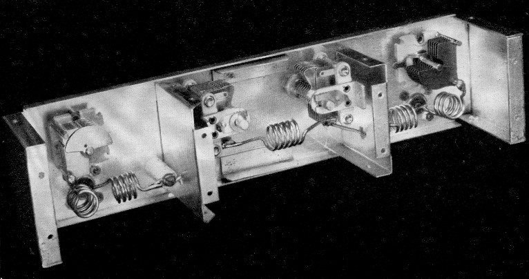
A low-pass filter for use with a high-powered 50 Mc transmitter. Though variable condensers are used, they are not adjusted in normal operation, and shafts should be anchored in place with lacquer to prevent their being moved accidentally.
Often the interfering harmonics will be passed on through succeeding stages, particularly with the capacity-coupled circuits so often used in frequency multipliers, so shielding alone may not effect a cure. But just as with other forms of harmonic trouble, shielding is the first step in a corrective program. You have to have it before other measures will work.
The more stubborn cases
What to do from here on depends on the severity of the problem. If your harmonic TVI (either from exciter stages or the final operating frequency) is just a matter of faint cross-hatching, it is quite possible that shielding the rig and installing an antenna coupler fed with coaxial line(1) may clear it up, as these simple steps are capable of holding down radiation of the harmonic by the antenna system to quite low levels.
If these measures make little or no change in the intensity of the interference, filtering of the power cables is next in order. As simple a matter as by-passing power leads where they are brought out of the transmitter enclosure may help, though use of shielded wire for interior power wiring, and the addition of small ceramic bypasses where the leads are brought out, as suggested by Grammer,(2) is much better.
In all but the more difficult cases, trouble will have been corrected by now, and in any event the strength of the harmonic interference will have been reduced to the point where it will be possible to track down the source. The simplest way to do this is to have a TV receiver running in close proximity to the transmitter, and use it as a visual indication of the effectiveness of suppression measures. A probing lead can be clipped to the TV antenna lead (no electrical connection; just the capacity coupling will suffice) to check for harmonic leaks in the transmitter and its associated cabling. Couple the transmitter to a lamp or other dummy load and see if harmonic energy is present in the antenna line. If the power cabling shows appreciable harmonic energy, more effective filtering of the individual leads will be required.
The use of shielded wire and ceramic by-passes will take care of most low-band harmonic radiation from power leads, but where Channels 7 through 13 are involved, something better may be needed. The exciter and amplifier 'described by the writer in QST for September and December serve as a good example. This combination was substantially free of harmonic TVI in the low channels, but when it was operated on 50 Mc. in the presence of a weak signal on Channel 11 it wiped the picture completely out with its fourth harmonic. Furthermore, it did it with only the exciter running.
The probe test showed that the power cable was hot with 200-Me. energy, so the filter circuit of Fig. 1 was installed in each power lead. Even the smallest by-pass condensers of conventional construction have sufficient lead inductance to make them relatively ineffective at 200 Mc, so feed-through capacitors were used at C2. Then small v.h.f. chokes were inserted in series with the leads, and the ceramic by-passes left as they were originally, connected as shown in Fig. 1 and the photograph on page 17 of April, 1951, QST. These methods are not applicable to leads carrying more than about 400 volts, so we had to settle for something a bit less effective on the feed-through terminal for the 4-250A plate voltage. Here a high-voltage by-pass of the most compact construction we could find was mounted as close as possible to the feed-through bushing, and the connection made to it with copper strap to hold down lead inductance. There was still a faint trace of harmonic left on the terminal and cable, but it did not interfere seriously except when the probe was held near the lead or terminal. These Channel 11 tests were made with a very snowy signal, with the 50-Me. transmitter only six feet away from the receiver, running inputs -up to 750 watts.
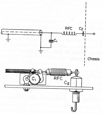
Fig. 1. Filter method for suppressing high-band harmonics that might otherwise be radiated from power cabling. A typical physical arrangement is shown in the sketch.
| C1 | 1 nF miniature disk ceramic. |
| C2 | 1 nF feed-through by-pass (Erie Style 326). (For 500-2000 volt lead, substitute Plasticon Glass mike, LSG-251, for C1 and C2.) |
| RFC | 14 inches No. 26 enamel close-wound on 3/16 inch diam. form or resistor. |
Shielding requirements were more stringent for the 200-Me. harmonic than for lower frequencies. The covers on both units had to be screwed down tightly all the way around, as the slightest crack leaked enough 200 Mc r.f. to cause trouble. A hole in the side of the chassis for the ventilating fan, a source of no troublesome harmonic radiation at 54 to 86 Mc, had to be covered with screening to contain the 200 Mc harmonic.
Low-pass filters for 50 and 144 Mc
Having gotten the level of the harmonic radiation on Channels 2 through 13 down to the point where very little could be found other than in the transmitter output load, we were ready to go to work on low-pass filters designed especially for the v.h.f. man. The filters shown in the photographs were designed according to information presented about two years ago in QST.(3) They use standard parts, and the adjustment procedure is simple enough if one has access to a grid-dip meter. Even without adjustment it is quite possible to achieve satisfactory results with these filters if the physical and electrical specifications given are followed closely.
The larger of the two is suitable for use with the high-powered amplifier for 50, 28 and 21 Mc., described in December QST, providing protection of Channels 3 through 13. Appreciable attenuation across the whole of Channel 2 is not practical for a filter that will also pass the 50 Mc band without insertion loss. Any of the commercial filters, or the various designs that have appeared in QST and the Handbook, can be used to reduce harmonics of the two lower bands in the amplifier's range, if Channel 2 must be protected. Such a conventional filter must be removed when operation on 50 Mc. is to be attempted.
The small filter is intended for use with low-powered 2 meter rigs, primarily to attenuate the 192 Mc component in the output that so often is present as the result of stages that triple to 144 Mc passing along a 4th harmonic of 48 Mc as well. Since it has high attenuation in the region between 190 and 215 Mc., it may also serve nicely in a rig for 50 and 144 Mc, in preventing radiation of the 4th harmonic of 50 Mc. It will not, however, remove any spurious components in the transmitter output that might interfere with Channels 2 through 6.
Building and adjusting the 50 Mc filter
This is a "how-to-do-it" treatment. Discussion of the principles involved will not be repeated here, but it is strongly recommended that anyone unfamiliar with filter fundaments read basic information on this subject that has already been presented.(3) The material to follow will concern itself only with the practical application of earlier design ideas to the needs of the v.h.f. operator, giving only the practical information that will be necessary to insure duplication of the results achieved with the two filters shown.
The circuit used in both filters is shown in Fig. 2, with values of inductance and capacitance for the 50 Mc job given on the diagram. If means for arriving at these precise values are available, the components can be preset and the filter assembled and used without further adjustment. A method of using a grid-dip meter and simple standards for measurement of both C and L was outlined recently in QST.(4) If the builder is in doubt of his ability to do this, or if he does not have access to a grid-dip meter, a satisfactory job can be done by using exact duplicates of the parts and layout, and setting the condenser plates at the positions shown in the interior photograph.
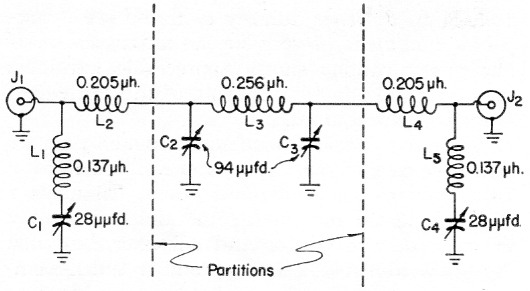
Fig. 2. Schematic diagram of the 50 and 144 Mc filters. No partitions are built into the 144 Mc unit. Values on the drawing are for the 50 Mc filter.
| C1,C4 | 50 Mc: 50 pF variable, shaft-mounted, set to middle of tuning range (Johnson 50L15). 144 Mc: 11 pF fixed ceramic (10 pF useable). |
| C2,C3 | 50 Mc: 100 pF variable, shaft-mounted, set with rotor 3 inch out of stator (Bud MC-905). 144 Mc: 38 pF stand-off by-pass (Erie Style 721A). |
| 50 Mc coil data: | |
|---|---|
| L1,L5 | 3½ turns 5/8 inch long. Top leads ¾ inch, bottom leads ¼ inch long. |
| L2,L4 | 4½ turns 5/8 inch long. Leads ½ inch long each end. |
| L3 | 5½ turns 7/8 inch long. Leads 1 inch long each. All 50 Mc coils No 12 tinned, ½ inch diam., coil length measured between right-angle bends where leads begin. |
| 144 Mc coil data: | |
| L1,L5 | 3 turns ¼ inch long. Leads ¼ inch long each end. |
| L2,L4 | 2 turns 1/8 inch long. Leads 1 inch long each end. |
| L3 | 5 turns ¾ inch long. Leads 5/8 inch long each end. All 144 Mc. coils No. 18 tinned, 4 inch diam., lengths measured as for 50 Mc, coils. |
| J1,J2 | Coaxial fitting. |
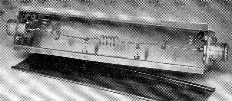
The 50 Mc filter case is a standard ICA box (Slip Cover, No. 29100), though a suitable container can be made from the dimensions given in the layout drawing, Fig. 3. Physical layout of parts is important, if results obtained with the original are to be duplicated without extensive adjustments. It is suggested that the drawing and photographs be studied carefully with this in mind.
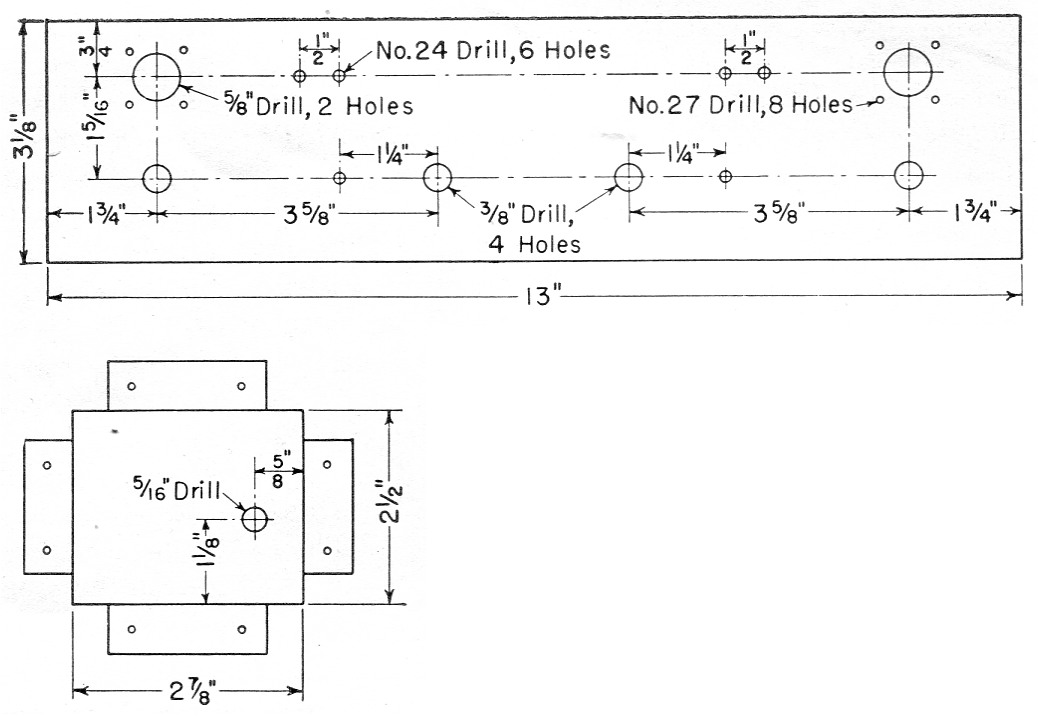
Fig. 3. Layout drawing for drilling the 50 Mc filter case and partitions.
Looking at the interior view, it will be seen that the two end condensers, C1 and C4, are mounted with their two stator posts toward the ends of the filter. The two larger units are mounted in the center compartment with their rotor shafts toward the middle. The top leads from coils L1 and L5 are wrapped around the stator terminals of C1 and C4, and the bottom leads fit directly into the coaxial input and output fittings. The outer ends of coils L2 and L4. are soldered to the coaxial fitting terminals, and their inner ends are soldered to lugs supported on one-inch ceramic stand-off insulators. Leads from the standoffs go through holes in the partitions to the bottom stator lugs on C2 and C3. L3 is soldered to the two upper lugs on these two capacitors, thus completing the filter circuit. Note that in addition to turns data, lead lengths for the coils are given in the parts list. These are the total lengths to be left when the winding is completed, including the portions that will be used in soldering operations.
If the components used in the original model are duplicated exactly it should be possible to set up the filter without the use of instruments and obtain usable results, though following through on the recommended adjustment procedure is a much more satisfactory approach. Using standard coils and condensers and a grid-dip meter in the manner outlined by Grammer,(4) the coils and condensers in the filter assembly were adjusted to the values given in the schematic diagram. The value of 28 pF for C1 and C4 came at almost exactly the middle of their adjustment range. C2 and C3 reached 94 pF with their rotors extending out of the stators about ¼ inch on the side of the condensers nearest the wall of the filter case.
With these settings the filter attenuation curve begins to rise at about 55 Mc, reaching its peak in Channel 6 but providing a useful degree of attenuation in all channels from 3 up. The rejection is high all across the high band, 175 to 220 Mc. This range takes care of most of the spurious frequencies that are likely to be generated in a 50 Mc transmitter, and it will handle all harmonics in the TV range from lower amateur frequencies as well, except those falling in Channel 2.
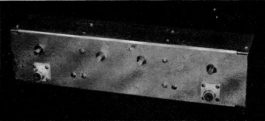
Interior view of the 50 Mc low-pass filter. End sections are of identical construction.
The 2 meter filter
Values of inductance needed in a 2 meter filter are too small to be very readily obtained by the methods outlined for the 50 Mc job, so a somewhat different approach is used. The filter was made in sections, using capacity values determined in advance and then adjusting the inductances to achieve resonance at the desired frequencies.
The case for the small filter was made of flashing copper. Dimensions are not particularly critical, but in this instance the box is 1¼ inche square and 7_1/8 inches long. The main portion of the case is cut from a single piece of copper, with the end tabs folded down and soldered to the sides. Flanges are folded over at the bottom, and a cover is made to slip over these. Details of the construction are visible in the photograph. Coaxial fittings are mounted in the middle of each end piece.
Low-pass filter for use with low-powered 144 Mc transmitters. Maximum attenuation is in the region of 190 to 215 Mc, but good from 170 Mc up.
Optimum capacitance values figured out to be 11 µpfd. for the end sections and 38 µpfd. for the middle ones. If a device for measuring capacity values accurately is available, standard 10- and 35- or 39 pF units can be measured and those coming nearest the desired values used. Stand-off type by-passes are ideal for this sort of work because of their minimum lead inductance, but suitable values of that kind of unit were not available for the end sections, so ordinary "dog bone" ceramics were used for C1 and C4. Several of these were measured and two nearest to 11 pF were selected. The center capacitors, C2 and C3, were stand-off units marked for 35 pF, though the actual value was slightly higher. Values as much as 10 per cent away from the optimum given under Fig. 2 should not make a large difference in results, if the adjustment procedure outlined below is followed.
The filter is assembled and adjusted in sections. First, L1 and C1 are mounted in place. A direct short is made across the input connector, J1, and the inductance of L1 is adjusted so that it and C1 resonate at 200 Mc. Then, connect in L2 and C2, removing the short from J1. The circuit including C1, L2, L2 and C2 should be adjusted (by adjusting the turn spacing of L2) to resonate at 144 Mc. Now disconnect L2 from C2 and mount L3 between C2 and C3. Adjust the turns of this winding until it resonates at 112 Mc. Mount L6 and C4 and adjust, as for the opposite end, with the coax terminal, J2, shorted. Add L4 and C3, as for the other end. Now connect all parts and check resonance with the grid-dip meter. The dip, all through the filter, should now be at about 160 Mc., the approximate cut-off frequency.
How about U.H.F. tvi
Tests conducted in the ARRL lab and elsewhere, and results so far obtained in Portland and Bridgeport, the only two areas where u.h.f. TV has been in operation for extended periods, indicate that the advent of u.h.f. TV generally will alleviate rather than increase our TVI problems. Certainly this is true for the user of the frequencies below 30 Mc. The order of harmonic, even from 28 Mc, that will appear in the u.h.f. TV range is so high that there should not be much trouble ordinarily. The 4-250A rig on 28 Mc made no TVI in a lab u.h.f. check.
The v.h.f. man is more likely to run into TVI trouble, however, as the order of his harmonics in the u.h.f. range is not so high. No means were available for checking the attenuation of the filters described at frequencies higher than 250 Mc., but indications obtained with various u.h.f. TV receiving set-ups are that the filters help materially when harmonics do show up.
The crystal diodes commonly used as mixers in u.h.f. TV receivers have the unhappy faculty of generating harmonics on their own, when strong r.f. fields are present. Preliminary checks indicate that harmonics up to the 10th or higher may be generated in this way. Like the first five items listed on page 16, this is a receiver fault. As such it will be dealt within a subsequent article.
There is one aspect of u.h.f. TV that should make our problems somewhat simpler than those we've learned to live with in our experience with Channels 2-13: Where high-order harmonics are involved, a small change of transmitter frequency shifts the offending harmonic out of a locally-used channel. The 10th harmonic of 50 Mc is the first one to appear in the u.h.f. range, so a change of 200 kc in the operating frequency should be enough to move the interference out of the critical spot in the channel. Even the 4th harmonic of a 144 Mc rig, the lowest that could interfere directly with a TV signal, could be moved out of trouble in Channel 31 without too great a change at the operating frequency.
We will run into some new problems when u.h.f. TV gets going in high gear, but after the progress we've made in the last few years, who can doubt that any troublesome circumstances arising from u.h.f. expansion will be solved in short order?
Notes
- Antenna couplers for 50 and 144 Mc were described in QST for October, 1952, p. 58, and January, 1952, p. 50.
- Grammer, "By-passing for harmonic reduction," QST, April, 1951, p. 17.
- Grammer, "Eliminating TVI with low-pass filters," QST, Feb., March, April, 1950.
- Grammer, "Inexpensive L and C Standards," QST, Jan., 1953, p. 48.
Edward P. TiltonN* W1HDQ.