Remote tuning for the high-c VFO
A compact control unit for mobile installations.
Previous articles in QST have described an easy method of remotely tuning the Clapp type of VFO. Now W2GDW comes along with an even simpler arrangement for remote tuning of the high-C oscillator. From the viewpoint of the mobiler, one of the outstanding features is that the control-box element can be reduced to the dimensions of a single variable condenser on the dashboard!
The conveniences of VFO operation, once enjoyed, are hard to do without, and when a transmitter was obtained for use as a ten-meter mobile rig, it was felt necessary to provide for this flexibility. The rig is a commercial f.m. police unit, and multiplies the crystal frequency 18 times. It was decided that the frequency control belonged up front at the operating position, and that the VFO proper should be in the trunk of the car, with the transmitter.
The idea of a remotely-controlled, motor-driven VFO tuning condenser was rejected for several reasons. The ability to set frequency closely seemed doubtful; a motor drive with a gear ratio which would allow accurate zero-beating would turn too slowly when tuning across the band, the gears would have to have a minimum of backlash, and considerable complexity would be required to include a frequency indicator at the control position.
A remotely-tuned Clapp oscillator, several embodiments of which have appeared in QST(1) and other publications, has the advantage of good voltage stability, but was considered undesirable for other reasons. The output of the series-tuned oscillator varies over the band and, more important, considerable care is required in order to prevent deterioration of the tank-coil Q. Thus a very large control box is required to house the oscillator tuning condenser and tank coil, and the box must be placed at the driving position, where space is at a premium. The much smaller unit containing the tubes is placed in the trunk, where space is relatively abundant. Also, with the low-C circuit, the problem of reducing the effects of mechanical vibration, especially in mobile work, is not always solved easily.
High-c VFO
A remotely-tuned VFO featuring direct calibration, accurate and simple frequency setting, uniform output over the band, high stability, and small size at the operating position, has been developed and has proven an excellent solution to the problem of remote VFO control. The basis for this VFO is an oscillator frequency low enough that the tank capacitance may be split up and placed in several locations. In this particular transmitter the oscillator frequency is 1.6 Mc. A high-C Colpitts oscillator for this frequency may be built with about 2100 pF of tank capacitance. As shown in the schematic, Fig. 1, about 1425 pF is placed directly across the tank coil, in the form of the bandset condenser (25 pF), the padding condensers (1090 pF), and the series combination of the Colpitts feedback condensers (equivalent to 310 pF). Another 140 pF is provided by the VFO tuning condenser. The remaining 500 pF is made up by the twenty-foot length of RG-59/U cable (25 pF per foot) which connects the VFO unit in the trunk to the VFO tuning condenser at the operating position.
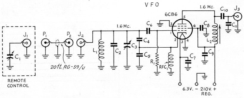
Fig. 1. Circuit of the remotely-controlled high-C VFO.
| C1 | 140 pF variable. |
| C2 | 1.09 nF silvered mica (910 pF and 180 pF units in parallel). |
| C3 | 50 pF variable. |
| C4 | 470 pF silvered mica. |
| C5 | 910 pF silvered mica. |
| C6 | 100 pF silvered mica. |
| C7,C8,C9 | 10 nF disk ceramic. |
| C10 | 300 pF mica. |
| C11 | 56 pF (see text). |
| R1 | 47 kΩ, ½ watt. |
| L1 | 20 turns No. 12, 1 inch diam., 1_3/8 inch long. |
| L2 | Approx. 90 µH (CTC 1-Mc. slug-tuned coil with turns removed to resonate at approximately 1600 kc.). |
| J1,J2,J3 | Female coax connector. |
| P1,P2 | Male coax connector. |
| RFC1 | 2.5 mH r.f. choke. |
The VFO unit, as indicated in Fig. 1, consists of a single 6CB6 Colpitts oscillator. The tank coil, which for a Colpitts oscillator does not require as much attention to Q as does the coil of a Clapp oscillator, is placed in the VFO unit. The remote VFO tuning unit consists solely of the 140 pF tuning capacitor! The main unit, which can be placed wherever space is available, includes, in addition to the remainder of the oscillator components, a small vibrator supply, VR tubes, and switching and control circuits. The VFO control box includes the remote tuning capacitor, direct-reading calibrated dial, control switches, grid-drive meter, and the microphone jack.
Control box
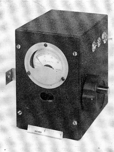
As shown in the photographs, the control box contains the VFO tuning capacitor, a microphone jack, a switch to actuate a VFO-crystal relay in the transmitter, and a switch to disable the transmitter when zero-beating. A meter is included to monitor grid drive to the 807 final stage. In addition to acting as a continuous check on the general operation of the transmitter, this meter also serves another useful purpose. Inasmuch as the transmitter is in the trunk of the car, and necessarily tuned to a particular frequency, it is important to know if the chosen operating frequency is sufficiently close to the frequency to which the transmitter is tuned. This is readily shown by the grid-drive meter. The particular transmitter used is sufficiently broad-band that the operating frequency may be swung over a 600-kc. range (half of the 10 meter band) without requiring retuning of the transmitter.
The housing is a standard 4 × 5 × 6-inch metal box. This box is larger than is actually required, and if one were interested in a very small VFO control, the box could be one just large enough to contain C1, the tuning condenser. In that event, the meter, switches, and microphone jack would be located elsewhere.
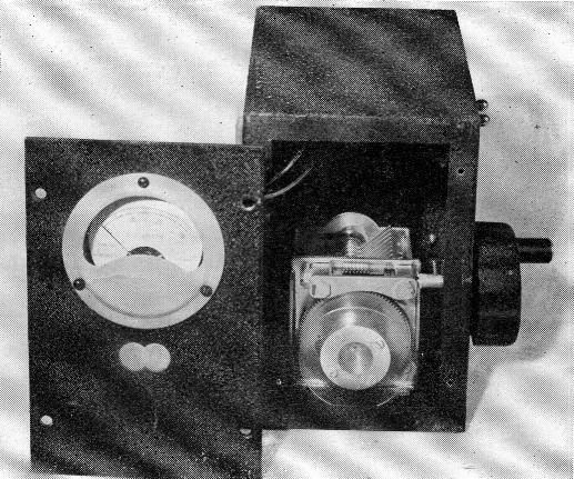
Interior of the remote-control box, showing the tuning-condenser dial ready for its calibrated scale.
A compact dashboard unit for remote control of a VFO rig. Included in this model are also a meter for checking output-stage grid current and switches for remote power and changeover control. The jack is for microphone connection.
In this instance the tuning condenser, C1, is one of the type used in the BC-221 frequency meter, and the knob is one of the type used on the BC-348 receiver. The gear ratio is such that the complete tuning range of the tuning capacitor is covered in 45 revolutions of the tuning knob. The entire tuning range is easily covered in about ten seconds, and yet the worm drive offers accuracy of zero beating and excellent mechanical stability under the rigors of mobile operation. A plastic disk is shown attached to the shaft on which the rotor plates are mounted; the frequency calibration is mounted on this disk, and viewed through the indicator hole in the front panel. (At the time the pictures were taken the calibration card had not been mounted.) The shape of the condenser plates is such that the calibration is linear with frequency.
A small aluminum bracket is used to mount the control box to the steering column of the car. On the rear panel of the box, not shown in the photos, is an octal connector for the control cable to the trunk, a separate "phono"-type jack for the shielded microphone cable, and a standard 83-1SP coaxial connector for the 20-foot coaxial cable which goes to the VFO unit in the trunk.
VFO unit
Photographs show the essential details of the assembly of the VFO unit. A U-shaped aluminum chassis is used, on the top surface of which are mounted the 6CB6 oscillator tube, two OB2 regulator tubes, and a small vibrator supply. A pushto-talk relay, the band-set condenser, and VFO tank coil are mounted inside, along with the small components, while a fuse and connectors are along the sides of the U.
The 1090 pF capacitor, made of 910 pF and 180 pF units in parallel, is mounted directly across the tank coil, and may be seen, in the bottom-view photograph, between the coil and the output coaxial connector. The slug-tuned coil in the plate of the 6CB6 is shown in the same illustration, below and to the left of the 6CB6 socket. In the interest of mechanical stability, No. 12 wire was used for wiring leads to the tank coil, the bandset trimmer, and the input coaxial connector.
Power supply
Any power supply delivering 200 to 250 volts at 8 to 10 mA may be used to operate this VFO. The author operated a breadboard model of the VFO and a crystal-controlled 10 meter converter on three 67½ volt Mini-Max B batteries for several months with no noticeable effect on the bat teries. In the final model, the vibrator supply (liberated from an old Chevrolet auto radio) has been incorporated.
Adjustment
Adjustment of the VFO is quite simple. Set the tuning capacitor C1 to minimum, and adjust C2 until the oscillator signal is heard on the receiver at 29.7 Mc. That's all there is to it! If the coil and cable dimensions, and the component values in the tank circuits have been followed closely, the VFO will now tune the 10-meter band. The author's VFO actually covers from 28.548 Mc. to 29.7 Mc.; the tank coil should be just slightly lower in inductance for 100 per cent coverage of the band, but the bottom 48 kc. was not considered important enough to be worth any priming of the coil. If a particular installation should require more or less than 20 feet of coaxial cable to link the VFO control to the main unit, the value of the padding condenser, C2, should be decreased or increased accordingly, at the rate of about 25 µµfd. per foot of cable.
The 6CB6 plate coil, L2, is resonated by C11, in parallel with approximately 2 feet of RG-59/U cable (50 pF) and a 68 pF capacitor from grid to ground in the crystal-oscillator stage of the transmitter which the VFO feeds. Again, if the cable from the VFO to the transmitter differs greatly from 2 feet in length, or if the capacitance shunting the input to the stage being fed is greater or less than 68 pF, the value of C11 or L2 should be changed accordingly. The Q of the plate tank is sufficiently low so that the VFO output is constant over its entire range. The output is 30 volts peak-to-peak across 47 kΩ.
Stability
Two tests of the short-term stability have been made. In a bench test following a ten-minute warm-up, the oscillator was placed in zero beat with a BC-221 frequency meter, and at the end of twenty minutes the oscillator frequency had drifted ten cycles. This represents a drift of 180 cycles at ten meters. Short-term stability has been measured while in mobile QSO with a fixed station by zero-beating the b.f.o. of the fixed-station receiver with the transmitter-VFO signal. Variations of about 200 cycles were noted. A lock on the control knob thus appears unnecessary for purposes of in-motion stability.
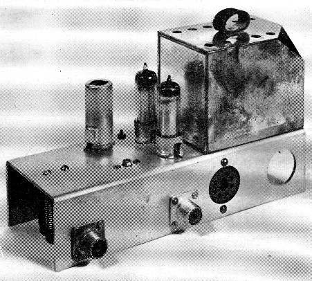
The main VFO unit may be placed in the trunk or other available space. It includes a small vibrator pack, the 6CB6 oscillator tube and a pair of voltage-regulator tubes. Coax connectors are provided for connecting to the remote tuning cable and to the input stage of the transmitter.
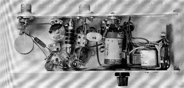
Bottom view of the main VFO unit. The midget variable toward the left is the handset condenser, C3. The coil at the left is wound on polystyrene rod.
The basic principle of separating the tuning capacitor from the VFO proper by a length of coaxial cable, the capacitance of which constitutes a portion of the tank capacitance, may be applied at frequencies other than the one described here. Two limitations present themselves: The length of the cable should be less than % wavelength at the VFO operating frequency and, for stability, the capacitance of the cable should not constitute the major portion of the capacitance across the tank coil. In addition, if an electrically-long cable length is contemplated, there may be tendency for the end at the control box to be "hot," and adequate grounding of the control box and VFO to the car frame should be assured.
Notes
- Long, "Cutting down VFO drift," QST, Aug., 1952, p. 20.
Mix, "Simple remote tuning for the VFO," QST, Jan., 1953, p. 27.
N.D. Larky, W2GDW.