Supplementary data on the r.f. assembly for mobile or fixed-station work
Operation with 12 volt ignition systems; also other facts.
October, 1954, QST described an "R.F. assembly for mobile or fixed-station work," and the following issue - November - carried an article, "Audio for the mobile or fixed-station r.f. assembly." This equipment has attracted considerable-attention, judging from numerous comments and inquiries received here at Headquarters. As is frequently the case with equipment described in QST, several readers have asked for advice in making certain alterations in the original to suit their particular requirements. Many asked about conversion to 12-volt operation to suit some of the later-model cars. Others wanted to know if it might be feasible to add a second 6146 in parallel in the final amplifier. A few were interested in adapting the r.f. unit to VFO operation.
Some of these questions cannot be answered definitely until experimental work, now in progress, has been completed. In the meantime perhaps we can offer some suggestions to those who may wish to get started on their own.
Twelve volt operation
To adapt the r.f. assembly for 12-volt operation, it is only necessary to rewire the heater circuit as shown in Fig. 1. In this arrangement, the heaters for the 5763s are first connected in parallel and then tied in series with the heater for the 6146. To equalize the voltage distribution, a resistance of approximately 25 ohms is connected between Pins 2 and 7 of the 6146. The resistor will have to handle about 1.5 watts (6 volts at 0.25 amp.). To allow an adequate safety factor, a 5- or 10-watt resistor is recommended.
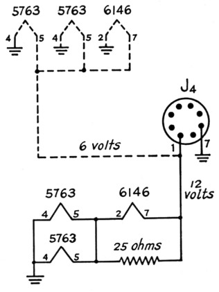
Fig. 1. Heater wiring for the r.f. assembly. Original wiring is shown in dotted lines and solid lines show wiring for 12 volt operation.
The audio unit may be revamped for 12-volt operation by using the series-parallel heater circuit shown in Fig. 2. This circuit uses the normal 12-volt connections for the 12AX7 and operates with the 6L6 heaters in series. Pin 9 of the 12AX7 is not used in the 12-volt arrangement.
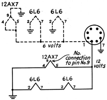
Fig. 2. 12 volt heater circuit for the modulator. Dashed and solid lines indicate original and revised wiring, respectively.
Increasing power
In the original r.f. assembly, space was left at one corner of the chassis for the installation of a small modulator, if desired at some future date. However, it appears that the empty space looks like about the right size for another 6146 to some of the fellows who are more interested in the unit for home-station use, than in mobile operation. Unfortunately, there are several factors involved besides the one of space.
Perhaps the most important question is the one of getting enough excitation from the oscillator to drive two tubes at full rating. Removal of the loading resistor from the driver plate circuit may help. However, this is bound to make tracking of the two multiband tuners more critical and may result in instability. Incidentally, a few readers could find no mention of R3 other than in the circuit diagram. Details of this resistor are given in the top righthand paragraph, page 15, of the October issue.
If the 6146s are to be connected in parallel, it is more than probable that the multiband tuners will require modification because of the increase in minimum input and output capacitances across the tanks. This may make necessary some trimming of the coils. Anyone attempting the conversion should read previous articles(1),(2) on the design of multiband tanks.
One more frequent repeater is the question concerning conversion of the 5763 oscillator for remotely-tuned VFO operation. From the standpoint of circuit modification, this does not present much of a problem and those interested should duplicate the oscillator section of Fig. 6-44 of The Radio Amateur's Handbook, 31st edition. This same circuit also appears on page 24 of QST for December, 1952. But selecting an oscillator schematic is not the complete problem as is indicated by the following.
The chances are pretty good that the output from the VFO set-up will be appreciably less than from the crystal-controlled arrangement and may not provide adequate drive for the 6146 final. This will most certainly be an important factor in any attempt to operate parallel 6146s.
The multiband tanks are quite sharp and require readjustment whenever the operating frequency is shifted appreciably. Therefore, a remote frequency-control head and a trunk-mounted transmitter would be rather inconvenient. Even though the retuning of the r.f. assembly is a simple job itself - thanks to the ganged multiband tuners - it is advisable to mount the unit so that the tuning controls are within reaching distance of the driver-operator. The original design of this transmitter was based on the assumption that the unit would be so located.
Additional notes
In closing, we should like to add several bits of information on points that have caused some constructors some concern. Two of these items appeared under the heading "Feed-back" on page 10 of the November, 1954, issue, but will be repeated here for the benefit of those who may have overlooked them.
In the parts list, page 12, October QST, L3 should be B & W Miniductor No. 3012 (not No. 3007 as shown).
In Fig. 2, page 14, October QST, the dimension (1/32) shown to the upper right of hole "C" should be changed to 25/32 inch.
To obtain cathode-bias protection for the oscillator (see page 12, October QST), the 0.1megohm oscillator grid leak should be returned to ground rather than to the cathode (Pin 7) of the 5763.
The knobs used on the r.f. circuit controls are E.F. Johnson type 116-222-1. They have a 100-0 scale spread over 180 degrees and have a 1_1/8 inch knob mounted on a 1½ inch skirt. Yes, they are available from some of the mail-order supply houses.
Notes
- Johnson, "Multiband tuning circuits," QST, July, 1954.
- Chambers, "Single-ended multiband tuners," QST, July, 1954.
C. Vernon Chambers, W1JEQ.