An S.W.R. indicator for transmission lines
Convenient unit with built-in generator.
The convenience of an s.w.r. indicator with a built-in signal generator was pointed out by W4ZG in QST for December, 1955. The unit described here represents another way of accomplishing a similar result.
Most transmitters do not include a means of reducing power to the level required for use with a standing-wave bridge of the inexpensive type, and such means are sometimes difficult to install. The unit shown in the photograph includes a signal generator so that antenna adjustments can be made independently of the transmitter. The r.f. generator may use any type of circuit preferred by the builder, but it should have good frequency stability and be capable of delivering at least one watt of power. The shielding should be adequate to prevent stray pickup when the instrument is used in the immediate field of an antenna.
One satisfactory source of r.f. power for bridge measurements is shown schematically in Fig. 1. It consists of a simple crystal oscillator with a frequency multiplier for the higher-frequency range. Crystals are very inexpensive and provide ample stability for this purpose. The frequency selected should fall in the approximate center of the band in which the antenna is to be operated.
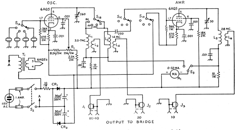
Fig. 1. Circuit of the signal generator for the s.w.r. bridge.
All capacitances less than 0.001 µf, are in pF. All 0.001 µF bypasses are disk ceramic. The 250 pF coupling capacitor is mica. Capacitors marked with polarity are electrolytic.
| CR1,CR2 | 100 mA 130 V selenium rectifier. |
| J1,J2,J3,J4 | Coaxial receptacle, UG-568/U or similar. |
| L1 | 25 turns No. 22, ¾ inch diam., 1¼ inches long. |
| L2 | 5 turns No. 24, close-wound 1/8 inch from bottom of L1. |
| L3 | 17 turns No. 22, ½ inch diam., ¾ inch long, tapped 5 turns from bottons end. |
| L4 | 4 turns No. 24, close-wound, 3/16 inch from bottom of L3. |
| L5 | 12 turns No. 18, ½ inch diam., ¾ inch long. |
| L6 | 3 turns No. 24, close-wound, spaced 1/8 inch from bottom of L5. |
| M1 | 0-50 d.c. milliammeter. |
| R1 | Output-control potentiometer. |
| S1 | 4 pole 4 position ceramic-insulated rotary. |
| S2 | D.p.s.t. toggle. |
| S3 | S.p.d.t. toggle. |
| T1 | Filament transformer: 6.3 V, 1 A required. |
The oscillator provides ample power for operating the bridge without the use of an amplifier stage and can be controlled directly by crystals operating in the 3.5, 7 or 14 Mc. amateur bands. A single doubler stage provides output in the 28 Mc. band. All band changing is accomplished by a four-pole, four-position band switch arranged to render the frequency multiplier inoperative when not required. The r.f. output power is adjusted by means of a potentiometer in the screen-grid supply circuit of the oscillator tube. Plate-andscreen power for the oscillator and multiplier tubes is obtained from selenium rectifiers in a voltage-doubling circuit. Notice that no portion of the power supply is connected to the chassis. This avoids the shock hazard and the danger of shorting the power line with grounded systems.
The oscillator plate tuning capacitor is sufficiently large to permit the coverage of both the 3.5 and 7 Mc. bands with one plate inductor. A second inductor is used for 14 and 28 Mc. operation. The output is link coupled from the oscillator plate coils for 3.5, 7 and 14 Mc., and from the doubler plate tank coil for 28 Mc. Separate output connectors are provided for each frequency range.
The bridge circuit (Fig. 2), which is more or less conventional, is provided with its own coaxial input and output connectors, permitting the use of an external r.f. generator, if desired.
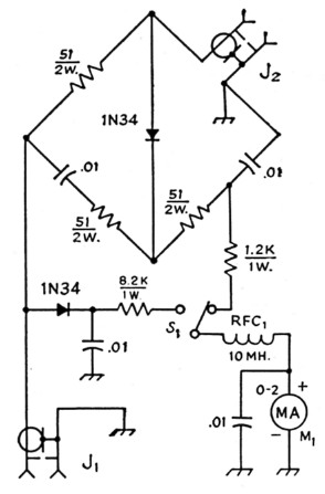
Fig. 2. Circuit of the s.w.r. bridge. All resistors are composition. Capacitors are ceramic and values are in µF.
| J1,J2 | Coaxial receptacle, SO-239. |
| M1 | 0-2 d.c. milliammeter. |
| S1 | S.p.d.t. toggle. |
The instrument shown was built into an aluminum case which originally held a surplus BC-187A radio transmitter. Any case of appropriate size and shielding ability will be equally satisfactory. If desired, the bridge and indicator system may be housed separately from the r.f. generator. Another convenient modification might involve a redesign into a completely self-contained portable instrument powered by dry-cell batteries. For such an instrument, the use of Type 3Q4 or Type 3V4 tubes is suggested.
With an instrument such as this available, many of the problems experienced in the use of coaxial transmission lines may be solved, and often simple antenna-matching systems may be used to replace the more complicated systems.
The theory of the s.w.r. bridge and its application have been covered in previous QST articles(1),(2) and in the last several editions of the ARRL Handbook.
In normal use little attention is given to the actual meter reading. Adjustments are made to the antenna feed system, working toward a zero meter reading. The instrument should be located as close to the antenna as is convenient, although the readings at the end of a long transmission line will follow in general the readings made at the antenna. Also, if the input level is always adjusted to the same value before each test, it will be easier to determine whether or not the last adjustment made to the antenna has resulted in an improved match.
Notes
- Caywood, "An improved antenna bridge," QST, August, 1955.
- Grammer, "Universal S.W.R. measurements with a coaxial bridge," QST, December, 1950.
James N. Whitaker, W6KRZ.