Let's increase V.F.O. stability
Reducing effects of temperature and vibration.
The proponents of series- and parallel-tuned v.f.o. circuits having battled to a draw on theoretical considerations, the author of this article now looks at the practical side. If you've been using a series-tuned circuit, this plug for a return to the old high-C Colpitts may interest you.
From listening to conversations on the amateur bands, one gets the impression that the average v.f.o. in use is not as stable as users might desire. The wider use of s.s.b. has put more stringent requirements on oscillator stability. This brings up the question of what can be done to improve the performance.
Most of the v.f.o.'s in operation today use the Clapp, or series-tuned Colpitts circuit. So far as stability with changes in tube characteristics and loading is concerned, the consensus now is that there is nothing to choose between the Clapp circuit and circuits of other configuration) With this point accepted, there are still other considerations that may make one type of circuit preferable to another in practice if not in theory.
Practical disadvantages of the series-tuned circuit
In the Clapp circuit, shown in most-common form in Fig. 1, the very low value of tuning capacitor, C1, causes one end of the inductor and its associated wiring to have a very high impedance to ground. Because of this, the small variation in capacitance which occurs when one of these parts moves mechanically in respect to ground, due to vibration or other movement, will cause a larger variation in frequency than would be the case if the impedance were lower. Most of us are familiar with the problem of preventing "microphonics" in a series-tuned circuit.
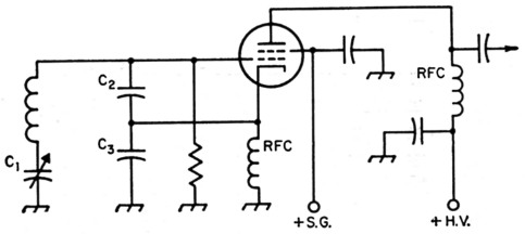
Fig. 1. Typical series-tuned Colpitts or Clapp oscillator circuit.
The search for the very high inductance required often leads to the use of inductors supported on plastic strips. These coils not only have very large temperature coefficients, but also poor retrace characteristics. That is to say, the temperature coefficient of inductance does not remain constant over a temperature cycle and varies from one cycle to another. The low thermal inertia of the fine wire used to wind a high value of inductance in small space, whether on a rigid form or not, gives rise to short-term frequency variations that can be very annoying.
In the case of a series-tuned circuit with a coil Q that is constant over the band being tuned, the tube gm required to maintain oscillation varies with the third power of the frequency.(2) From a practical standpoint, this means that the power output of the series-tuned oscillator is likely to vary considerably from one end of the band to the other.
The high-c oscillator
All of the foregoing problems can be minimized by a change to parallel tuning - in other words, a change to the old high-C Colpitts circuit, as shown in Fig. 2. The large swamping capacitances, C2 and C3, in series, as well as the tuning capacitor C1, are now in parallel with the inductance. This reduces the circuit impedance and thus the frequency variation due to mechanical movement of components associated with the ends of the coil. It also reduces the value of inductance needed to resonate with the capacitors at the desired frequency. This lower value of inductance can be wound with heavier wire which makes a more rugged mechanical unit of higher thermal inertia which reduces drift due to short-time heating effects.(3) The tube gm required to maintain oscillation in a parallel-tuned circuit varies inversely as the first power of the frequency.(2) Therefore, the power-output variation in tuning over a band should be much less than with the series circuit.
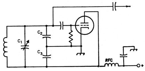
Fig. 2. Conventional Colpitts oscillator circuit.
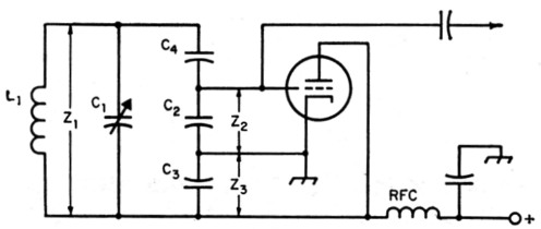
Fig. 3. Colpitts circuit modified to suit the value of tuning capacitor C1.
Electron coupling
There is also room for improvement in another respect. Most of the current v.f.o.s use the so-called "electron-coupled" circuit, as in Fig. 1. While this arrangement may save a slight amount of space, it has disadvantages. With the tubes ordinarily used, it is necessary to operate the cathode at some r.f. potential above ground. This is undesirable because it places the heater-cathode insulation across part of the tuned circuit. This insulation is the dielectric of a capacitor (sometimes with an associated leakage resistance) operating under very unsatisfactory thermal conditions.
With the electron coupled arrangement (screen grounded), the r.f. output plate current passes through part of the tuned circuit (C3) in returning to cathode. Under this condition, any harmonic content in the plate current can detract from the stability.(4)
Maximum output from the e.c.o. circuit requires a minimum impedance between cathode and ground. On the other hand, the frequency effect of the grid-cathode circuit of the tube is several times the effect of the cathode-ground circuit. Therefore, for maximum frequency stability, the larger swamping capacitance (lower impedance) should be across the grid-cathode circuit.
These considerations indicate that better stability should be obtained if the cathode is grounded, as shown in Fig. 2, and a separate amplifier used instead of the electron-coupled arrangement. Where space must be minimized, a triode-pentode (such as the 6U8) could he used for this purpose.
How Much C?
The maximum circuit capacitance that can be used will depend upon the tube g,,,, and the losses in the inductor. The latter increase rapidly as the inductor becomes very small. However, in a practical case, the capacitance will usually be limited by the physical size of the variable capacitor required to tune across the desired band of frequencies. The size of the tuning capacitor required varies in direct ratio with the amount of fixed capacitance in shunt with it. Without going to transmitting-type variables, the largest variable capacitor commonly available is the "MC" type which is obtainable in units having maximum capacitances up to 325 µµf. and a capacitance variation (maximum capacitance minus the minimum capacitance) of 300 µµf. These units are quite reasonable in physical dimensions.
Calculations of other tank-circuit values for a range of 1.75 to 2 Mc, based on a variation of 300 pF are shown in the appendix.
Should it turn out that the design has been too conservative, and the circuit superregenerates, it is only necessary to decrease the value of C4 and connect additional capacitance across the entire circuit to restore the proper frequency range. If the error is in the opposite direction, and oscillation is not maintained across the entire band, the value of C4 should be increased and the value of C2 or C3 decreased until the frequency range is correct. Similar calculations can be made for the range of 3.5 to 4 Mc. However, if the minimum circuit capacitance of 1000 pF is maintained, the inductance will have to be reduced to 1.75 µH. At an inductance this low, it may be impossible to obtain a coil of sufficiently high Q to maintain oscillation with a tube of average gm. In this case, the design should be based on a smaller tuning capacitor.
Fixed capacitances should be made up of suitable combinations of silver-mica or TCZ units to provide the correct values. The best type of inductors temperaturewise are wound with heavy wire under tension on ceramic forms.
Although the high-C circuit can be operated with the tube remote from the tuned circuit as easily as with the Clapp arrangement, best stability should be obtained with the tube and circuit close together. Only a slight separation will provide adequate heat isolation, especially if heat baffling is used.
A practical circuit
Fig. 4 shows a practical circuit using the values worked out in the appendix. The triode-connected 6AU6 has a rated g,n of 4500. The oscillator feeds a Class A pentode amplifier using another 6AU6. It is recommended that the plate supply to the oscillator and screen supply to the amplifier be regulated. If low-impedance output is desired, a Class A cathode follower may be substituted for the grounded-cathode amplifier, although the output voltage will be less. Also, the follower provides less isolation between the oscillator and the load and therefore the load on the cathode follower should be fixed.
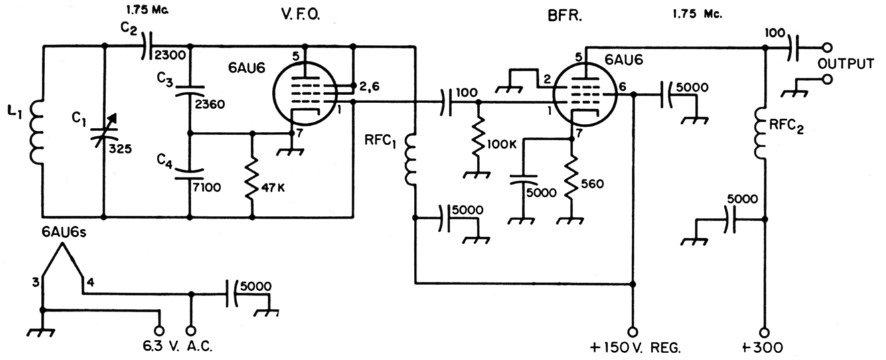
Fig. 4. Practical circuit for a high-C Colpitts v.f.o., including a Class A buffer. All capacitances are in pF. All 5000 pF capacitors are disk ceramic. All 100 pF capacitors may be mica or low-temp. ceramic. All resistors are ½ watt.
| C1 | 325 pF midget variable (Hammarlund MC-325-M). |
| C2,C3,C4 | See text and appendix. |
| L1 | Approx. 6.4 µH - 15 turns No. 12, 2 inches diam., 2 inches long. |
| RFC1,RFC2 | 2.5 mH r.f. choke. |
Appendix
To cover a desired frequency range, the ratio of minimum circuit capacitance to maximum circuit capacitance must be the square of the ratio of the maximum frequency to the minimum frequency. If the frequency range is to be 1.75 to 2 Mc., the frequency ratio is 2/1.75 = 1.14. The capacitance range required is 1.142 = 1.3
If a tuning capacitor having a variation of 300 µµf. is used, the minimum circuit capacitance must be such that when 300 pF is added to it, the capacitance will be 1.3 times the minimum capacitance.
C2 + 300 = 1.3 C.
0.3 C2 = 300
C2 = 1000 pF.
This should be the capacitance across L1 (Fig. 4) with C1 set at minimum capacitance. L1 should have an inductance that will resonate at 2 Mc. with 1000 pF - approximately 6.5 µH. The variable C1 then adds 300 pF which should tune the circuit to 1750 kc.
The criterion for oscillation in a Colpitts circuit is:![]()
where gm is the transconductance of the tube in µmhos, and Z2 and Z3 are the impedances offered to the grid and plate of the tube, respectively. To allow for losses, we can select a value lower than average for gm - 2000 µmhos.(5)
To equalize the effects of the grid-cathode and plate-cathode circuits of the tube on frequency stability, the impedance from grid to cathode should be much lower than from plate to cathode. Let us say that the plate-cathode impedance, 23, should be 9 times the grid-cathode impedance, Z2. Then:
![]()
The over-all circuit impedance is given by:
Z1 = QXC2
where Q is essentially the Q of the inductor, and XC2 is the reactance of the circuit capacitance. At 2000 kc., the circuit capacitance is 1000 pF, giving a reactance of 80 ohms. Assuming a conservative value of 100 for Q,
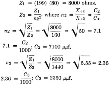
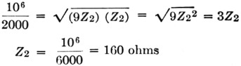
The resultant of C2 and C3 in series is
![]()
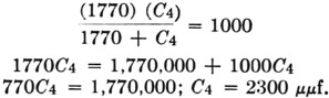
Since the foregoing values were based on a circuit capacitance of Cx = 1000 pF, a capacitor, C4, must be placed in series with C2 and C3 to reduce the circuit capacitance to this figure.
Notes
- Proceedings of the IRE, July, August, 1955.
- Clapp, "Frequency stable LC oscillators," Proc., IRE, Aug., 1954.
- In practice, this factor depends to a considerable extent on the design and construction of the coil. - Ed.
- Llewellyn, "Constant frequency oscillators," Proc. IRE, Dec., 1931
- See Howson, "Designing the V.F.O.," QST, Dec., 1955, for a discussion of effective transconductance.
W.B. Bernard, W4ELZ.