Improved control circuit for regulated power supplies
Using a cathode follower to increase control range.
By inserting a cathode follower between the control tube and the regulator tube in an electronic voltage regulator, the regulator tube can be 13 driven into the positive-grid region to increase the current range over which regulation can be maintained. The article also describes a novel power supply circuit in which the regulator tubes are the rectifiers.
A regulated power supply has three parts: first, an unregulated supply whose voltage is higher than that required; second, a series tube or several tubes in parallel which act as a variable resistance in series with the unregulated voltage to cut it down to the desired value; and third, a control stage which compares the actual output voltage with a fixed reference voltage and then changes the resistance of the series tube(s) in such a way as to bring the output voltage as close as possible to the desired value.
Fig. 1 is a simplified diagram of a conventional power-supply regulator circuit. The output voltage will be equal to the unregulated input voltage minus the drop across the series tube V1. For a given load current there are two limitations on the drop across V1. The upper limit is the voltage at which the rated plate dissipation of the tube is reached and is a property of the tube used. If this limit is reached, more output current can be obtained either by using two tubes in parallel or by lowering the unregulated voltage. The lower limit is the plate-to-cathode voltage at the time when the grid voltage, normally negative with respect to cathode, becomes zero. At zero grid voltage the resistance of the series tube is as low as it is going to get, and for that value of load current we will not be able to get any more output voltage unless more tubes are added in parallel with V1 or the unregulated supply voltage is increased. This limitation is not the fault of the series tube, V1, but of the control stage, which cannot supply appreciable grid current to V1. The load resistance, R1, for the control tube, V2, is made high so that the gain of the control stage will be high, thus giving a higher degree of regulation. This essentially limits the operation of V1 to the negative grid region since grid current for V1 must flow through R1, not through V2.
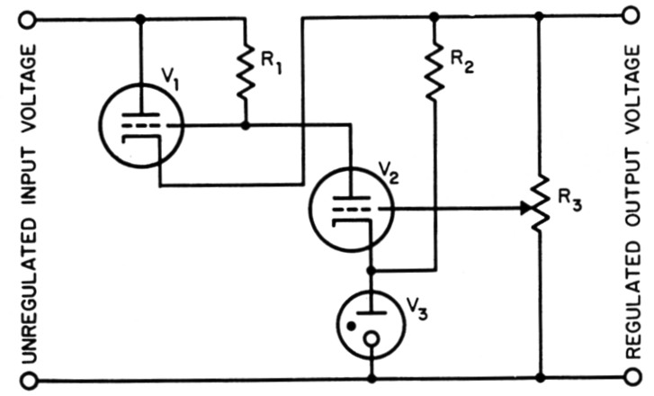
Fig. 1. Conventional electronic voltage regulator for power supplies.
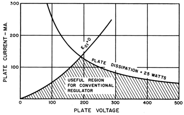
Fig. 2. Static characteristics of the 1625, triode connected. In a conventional regulator, only the region below Eg1 = 0 and below plate dissipation = 25 watt (30 watt ICAS) can be used. This means that current is limited to a maximum of 130 mA per tube.
Cathode-follower drive
It isn't really essential to operate the series tube in the negative grid region. To supply grid current to Vi we must provide a path from the positive side of the unregulated supply to the grid of V1. R1 provides this path but to supply appreciable grid current its value must be made low, which will reduce the gain of V2 and impair the regulation. A more satisfactory approach is shown in Fig. 3. A cathode follower, V4, which in most cases can be a 6C4, reproduces the voltage appearing at the plate of V2 but in addition supplies grid current to V1 when needed. R4 provides a load for V4 when grid current is not needed for V1. Its value is not critical; 1 megohm seems convenient. Incidentally, this stage - consisting of three junk-box type components, a tube, a socket, and a small resistor - can be added to almost any existing regulated power supply to increase the voltage available at higher current or the current available at higher voltages, however you want to look at it. The extra tube can be supplied from the same heater transformer as the series tubes without danger of heater to cathode breakdown. If possible, it should not be supplied from a heater winding which is grounded.(1)
Regulators as rectifiers
Like any circuit using a vacuum tube, the regulators shown in Figs. 1 and 3 act as rectifiers as well as performing their regular function. We can take advantage of this by replacing the unregulated d.c. source with an a.c. source. In this case, V1 will conduct over the part of the cycle when its plate is positive with respect to its cathode. If the a.c. voltage is great enough and the load current small enough, V1 will act as a regulator over part of the a.c. cycle and will limit the output voltage to a value dependent on the setting of R3. During the part of the cycle when the input voltage is great enough for rectifying action but not great enough for regulating action, V2 will be cut off, V1 will act as a straight rectifier and V4 will connect the grid of V1 to the input voltage to improve the rectifying action. Here the cathode follower, V4, not only allows more current to be delivered for the reasons explained previously but it also allows V1 to act as a regulator over a greater fraction of the a.c. cycle. This makes the output easier to filter, as will be shown.
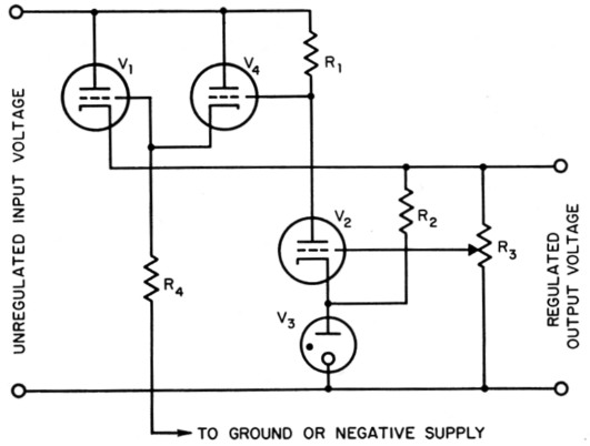
Fig. 3. Regulator circuit using a cathode follower, V4, to supply grid current to the series regulator tube, V1.
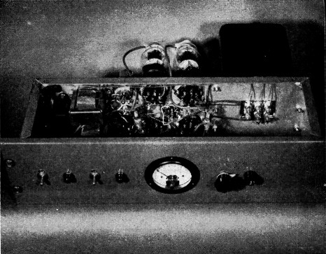
W1PLJ's regulated supply uses dish-type rack construction with a formed panel. The power transformer and tubes are on the rear chassis wall.
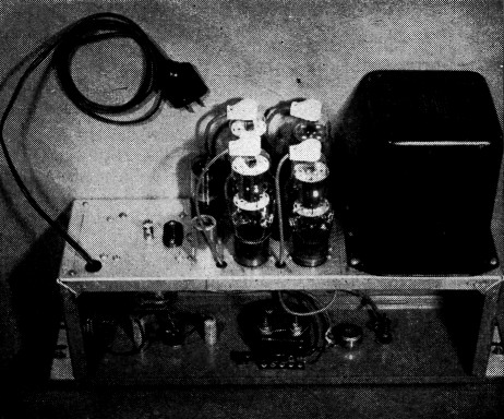
Looking inside the chassis of the power supply from the rear. This assembly includes everything except the filter capacitor, which is external. The power transformer shown is a surplus unit.
To make a practical power supply, two of the regulators shown in Fig. 3 would be connected to provide full-wave rectification. This is shown in Fig. 4. Only one reference source, V7, and control potentiometer, R3, are needed but the control amplifier and cathode follower are duplicated and are supplied from the transformer directly to avoid the need for a separate d.c. supply for them. In this way each control amplifier and cathode follower receives positive plate voltage only on the half of the cycle when it is needed, and the series tubes do not draw grid current on the half of the cycle when they are not conducting plate current.
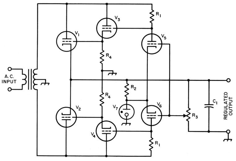
Fig. 4. Using two regulator circuits for the dual function of full-wave rectification and voltage regulation.
If no filtering is provided, the output will be "flat" over part of the cycle with a dip over the part when the series tubes lose regulation. The filter capacitor shown in Fig. 4 fills in this "dip" and the larger it is the purer the d.c. output. The ripple percentage can also be reduced by increasing the length of time the series tubes regulate as well as rectify. This is done by supplying a higher a.c. voltage from the transformer, setting the control for a lower output voltage, or adding more tubes in parallel with the series tubes. It would be nice if three-phase power could be obtained in the ham shack because three regulator circuits could be used and at least one of them would be conducting at any given time, so there would be no loss of regulation over any part of the cycle. With proper design little or no filtering would be needed.
Practical power supply for an S.S.B. linear
The power supply shown in Fig. 5 and in the photographs was built for a Class AB1 linear amplifier using two 6146s in parallel. It will deliver 630 volts at 250 mA with a change of only 15 volts from no load to full load, a degree of regulation better than is needed for the amplifier which it powers.
A neon bulb is used as a reference source and is supplied from the output through a 2.2 megohm resistor. A 12AX7 is used for both control amplifiers, with reference voltage applied to both cathodes and a fraction of the output voltage applied to both grids. A 6BL7 serves as a dual cathode follower and performs somewhat better than a 12AU7 or 6SN7 (which could also be used) because it will conduct more current at low plate voltage, thereby supplying more grid current to the 1625s and permitting them to act as regulators over a greater part of the cycle. The 47 ohm cathode resistors tend to divide the load equally between the 1625s as well as to prevent parasitic oscillations. It is important for the two sides of the circuit to be fairly closely balanced, because otherwise the ripple will contain a 60 cycle component which will not be filtered as effectively. The use of regular 10 per cent tolerance resistors of the same marked value for each function will make the balance close enough for all practical purposes. Pilot lamps (not shown in the diagram) are included in each 1625 plate lead to indicate relative balance and to act as fuses if a tube should short out.
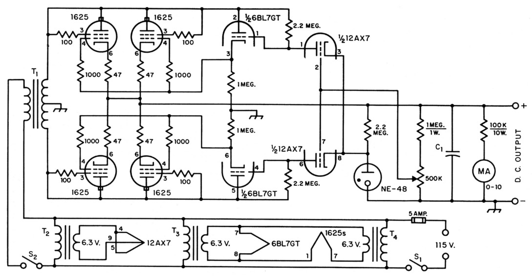
Fig. 5. Practical circuit for a regulated supply capable of delivering up to 250 mA at 600 V. Resistors are ½ watt unless otherwise specified.
| C1 | 30 µF or more, 1000 V (see text). |
| T1 | Power transformer, approx. 700 V each side c.t., 250 mA. |
| T2 | Filament transformer, 6.3 volt, 1 A. |
| T3,T4 | Filament transformer, 6.3 volts, 3 A. |
As in any power supply, the layout is not critical. At W1PLJ a Bud CB-1372 panel chassis was used with a Par-Metal P-602 formed panel. With this type of construction the tubes are available from the rear and the wiring can be reached from the front by removing the front panel without removing the chassis or disconnetting any leads. The filter capacitors are mounted on a separate chassis to make the main chassis easier to handle if changes are to be made.
Performance
The power supply shown will deliver any voltage from 300 to 630 volt at 250 mA and up to 900 volt at lower currents. Higher voltage could have been obtained with a higher voltage transformer. With a 30 µF filter capacitor ripple was 2 per cent at 600 volt and 250 mA. Ripple decreases with decreased load current and increases somewhat when the output voltage is reduced to 300 or 400 volts at 250 mA. With a 60 µF filter capacitor, ripple is 1 per cent at 600 volt and 250 mA. Dynamic regulation is excellent - no transient oscillations occur when the load is suddenly applied or removed. This is one of the difficulties with a choke-input power supply having insufficient inductance or insufficient output capacitance.(2)
Last but not least, this supply has the advantage that the voltage can be varied at the twist of a knob for tune-up or experimental uses.
Notes
- If this modification is to be made on W2VQL's power supply (" Really regulated," March, 1955, CQ), resistor R4 must be returned to the negative bias supply (Pins 2, 4, and 7 of the OB2), not to ground. To modify a Heathkit or other supply using 1619 series tubes, a 2.5 volt heater tube is needed unless another heater transformer is added. The 2BN4 seems to be the only miniature tube suitable here and a ¼ ohm dropping resistor will be needed for the heater. Again resistor R4 goes to the negative bias supply.
- GE Ham New, "About power supplies," January-February, 1954;
"More about power supplies," March-April, 1954.
Geiser, "The effect of capacitance on power supply filter bounce," QST, September, 1957. - Ed.
George W. Jones, W1PLJ.