Notes on the product detector
Measurements on "The poor man's signal slicer".
This is an article describing some experiments with the product detector, and the conclusions may benefit your E. present or future receiver. Here again is a good demonstration of the fact that in radio the circuit isn't everything; it's the way that you use it.
Several local hams have shown considerable AL interest in the "Poor Man's Signal Slicer,"(1) and many have reported improvement in receiver performance when using this device. After examining the original article, I concluded that the performance might not be as good as should be obtained, due primarily to excessive signal input. In addition, there has arisen a difference of opinion between certain hams as to whether W2CSY's circuit(2) is any better than a heterodyne detector (e.g., diode and b.f.o.).
When W3GKM constructed the circuit provided by Canter the opportunity was taken to make a few simple measurements to determine what demodulation characteristics are obtained.
An input signal of 455 kc., amplitude-modulated at 400 c.p.s., was applied to the input of the slicer, and the b.f.o. was adjusted so that the difference frequency between it and the signal carrier was 1000 c.p.s. A wave analyzer was used to measure the output of the slicer. If true product detection occurs the only output frequencies will be 600, 1000, and 1400 cycles per second. Nonlinearities of the type producing even harmonic distortion result in intermodulation components at 400 cycles per second and 800 cycles per second.
Intermodulation components occur in heterodyne linear detection, but they are primarily related to the size of the b.f.o. signal relative to the incoming signal and not to the detector characteristic.
Fig. 1 shows the results of the measurements. Fig. 1A shows the intermodulation components resulting from the a.m. signal side bands beating with the a.m. carrier and beating against one another. It is obvious that the signal input to the slicer must be maintained at a low level if such distortion is to be kept low. The b.f.o. signal likewise should be small for low distortion.
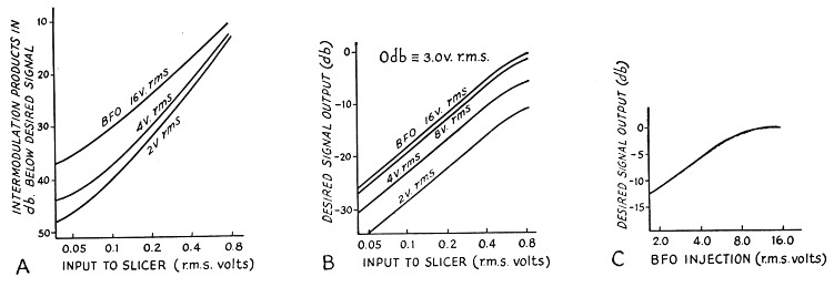
Fig. 1. Product-detector characteristics as observed by varying the signal input to a "Poor man's signal slicer."
Fig. 1C indicates that the output is proportional to the b.f.o. signal when the b.f.o. signal is small; at maximum b.f.o. injection the demodulator is operating as a cathode-coupled heterodyne detector rather than as a product detector. Referring to Fig. lA it is observed that product-detector operation produces about 10 dB less distortion than the heterodyne detector operation. When straining for QRP Europeans on 3.5 Mc. this 10 dB can be significant (if the receiver is linear up to the slicer).
The gain between the slicer input and the signal grid of the demodulator was 6_2/3 for this particular unit. Inputs to the product detector on the order of 2 volts r.m.s. for the b.f.o. and 0.1 to 0.3 volts r.m.s. for the signal are suggested. These voltages are somewhat lower than those recommended by Crosby, but are of the same order of magnitude. The corresponding level of the 455 kc. signal applied to the slicer will be 0.015 to 0.045 volts r.m.s. When proper input signal levels are employed the "Hybrid Detector" position of the slicer will not be of much use.
The usual communications receiver is designed to operate on a.m. with a normal signal level of 2 to 10 volts at the detector. An HRO-50 was to be used with the slicer. With the a.v.c. on, the voltage at the detector of the HRO was measured as 5 volts r.m.s. on strong signals. With the b.f.o. on, the a.v.c. is disconnected and the voltage exceeded 20 volts r.m.s. when the manual gain control was left at maximum. The b.f.o. injection voltage, however, was only 2 volts r.m.s.
At the plate of the last i.f. stage the voltage was between 10 and 20 volts r.m.s. on strong signals as the receiver was tuned across the 14 Mc. band. A 10 pF capacitor couples the i.f. signal from the last i.f. tube to the n.f.m. socket. The voltage at the n.f.m. socket was 3 to 6 volts r.m.s.; the reduction was due to the v.t.v.m. capacitance as well as the coax cable between the socket pin and the 10 pF capacitor. A shunt capacitor, C2, was added to the input to the slicer to reduce the voltage, as shown in Fig. 2.
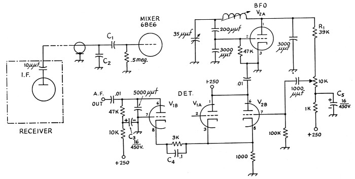
Fig. 2. Pertinent portions of the slicer discussed in the text. Values changed from the original are R1 and C1 through C5. Unless otherwise indicated, capacitances are in µF, resistances are in ohms, resistors are ½ watt.
| C1 | 100 pF. |
| C2 | 1000 to 3000 pF. Larger value will reduce distortion but also reduces output level. |
When this is done the receiver can be operated with the r.f. gain full on and a.v.c. "on." To avoid cross modulation caused by adjacent signals operating the a.v.c., the crystal filter should be used along with the signal slicer.
The a.v.c. circuits in the HRO are not entirely acceptable for s.s.b. and c.w. reception, but they do work to some degree in conjunction with the slicer when receiving such signals. A worthwhile modification to the HRO a.v.c. would be the circuit described by Luick.(3) This was not put in the HRO, but probably will be added at an early date.
One disadvantage of operating the signal slicer. as a product detector is that the audio output is small. This results from the fact that the device is an inefficient converter, but this is the price paid for the low distortion. Crosby indicates that the conversion gain of his unit is unity.(4) However, for low distortion the conversion gain that was realized in W3GKM's unit was -16 dB.
As noted on Fig. 1B, 0 dB was equivalent to 3 volts r.m.s. With the desired operating conditions for the slicer the audio output would only be about 60 millivolts for a 1000-cycle audio tone. With such a small signal hum problems may be encountered, and it is wise to add additional filtering on the voltage applied to the grounded grid amplifier. If the cathode capacitor in the grounded grid stage is increased in size, a worthwhile increase in audio is obtained.
In the plate of the grounded grid stage the 5000 pF filters the b.f.o. signal and i.f. signal components so that they do not saturate or introduce intermodulation distortion in the audio stages which follow the slicer. Such a capacitor, however, destroys the audio response. An increase in the size of the cathode capacitor reduces the the output impedance of the grounded grid stage so that a wider audio band width is obtained. Alternatively, some of the b.f.o. signal may be fed into the grid of the grounded grid stage(5) if still wider audio response is desired. The audio response, however, will be limited by the selectivity of the 50 kc. i.f. transformer.
B.F.O. injection
The maximum b.f.o. signal obtained with 250 volts plate supply was 13 volts r.m.s. If a linear potentiometer is used for b.f.o. injection then about one eighth rotation will give the suggested injection voltage. If desired, an additional resistor, R1, can be connected between the b.f.o. and the potentiometer, as shown in Fig. 2.
Operation of the product detector
If one signal is applied to a pair of resistors in series, and if the other signal (b.f.o.) varies one of the resistors so that its resistance is directly proportional to the instantaneous value of this signal (b.f.o.), the signal appearing across the variable resistor will be a modulated signal. If both signals are sinusoidal and if the variable resistance is very much lower than the fixed resistance, the resultant modulation will be distortionless. The product detector operates in such a fashion. The modulated signal consists of the i.f. signal modulating the b.f.o. signal. Side bands are generated, and if for simplicity we assume a single frequency in the i.f. signal, two side frequencies only are generated. One is the sum of the b.f.o. frequency and the i.f. signal; the other is the difference between the b.f.o. and the i.f. signal. The former is filtered out in the plate of the grounded grid stage, and the latter is the desired audio output.
An equivalent circuit for the product detector is shown in Fig. 3. The quantities rp3 and μ3 are constant. rp1, in and rp2, μ2 depend on the in stantaneous values of the b.f.o. and i.f. signal respectively. At the positive peak of the b.f.o. signal rp4 is a minimum, and because of the additional bias appearing on V1 due to the b.f.o. signal rp1 is a maximum. Similarly, at the negative peak of the b.f.o. signal, rp2 is a maximum and ro is a minimum. μl and μ2 also change slightly, but their effect is trivial. The i.f. signal also varies the rp of the b.f.o. cathode follower, but its effect in the modulation process is much smaller than that of the b.f.o. signal. It is this variation of the plate resistance of one of the cathode followers by the signal from the other cathode follower that results in modulation. A linear variation in plate resistance with grid voltage implies that the relationship between the plate current and the grid voltage is square law. By critical adjustment of the operating point of the tubes in the product detector it is possible to realize this condition more closely and obtain somewhat greater efficiency for the same distortion.
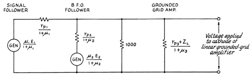
Fig. 3. The equivalent diagram of the product detector. The subscripts 1, 2 and 3 refer to the signal cathode follower, the b.f.o. cathode follower and the grounded-grid amplifier stage, respectively. Z1 is the plate load for the amplifier stage.
Admittedly, this is an inefficient detection process, but it does result in low distortion.
It is hoped that this note might result in a somewhat better performance of many of the "Poor man's signal slicer" units that have been built. The measurements reported here have convinced the writer that the receiver to be used in the 1958 DX test should incorporate the triple triode detector.
Notes
- Canter, "The poor man's signal slicer," QST, Dec., 1956, and QST, Jan., 1957, p. 26. (The "slicer" is connected just ahead of the detector in an ordinary receiver's 455 kc. i.f. amplifier. A crystal-controlled 6BE6 converter in the slicer heterodynes the signals to 50 kc., where they pass through two tuned circuits and then go to a product detector. Resultant audio output is fed back to the receiver's audio amplifier. - Ed.).
- Crosby, "Reception with product detector," QST, May, 1956.
- Luick, "Improved A.V.C. for side band and c.w," QST, Oct., 1957.
- Telephone conversation following MARS technical net broadcast on 7635 kc.
- Tech. Topic, "Transformerless balanced modulator for single side band," QST, February, 1957.
Dan Healey, W3HEC.