Adjustment of Gamma-Matched Parasitic Beams
Step procedure for on-the-ground tuning.
If it is true that experience is the best teacher, the author has had a higher education in the adjustment of parasitic beams. This article gives you the essence of what he has found out in the course of tuning up some dozens of such antennas on a wide variety of amateur bands.
After having sweated through countless hours of "adjusting the gamma match until the proper match is obtained" on some 40 assorted homemade parasitic beams from 2 to 20 meters, the conclusion is that this is easier said than done - and that some authors, including myself,(1) have been prone to underestimate the work involved.
This article concerns a single-band, 0.1 or 0.15 wavelength spaced, parasitic beam, coax fed and gamma matched - as simple and straightforward a system, mechanically and electrically, as can be devised.
The Gamma
Fig. 1A, the commonly used gamma-matched radiator, consists of loop ABCD to which is attached the half-wave radiator Eh'. The loop ABCD need not be rectangular, and Fig. 1B works precisely the same as Fig. 1 A as has been demonstrated many times. This latter really is Fig. 1C in disguise, the shunt-fed grounded quarter-wave radiator, familiar to the broadcast industry, and works on the principle that the one-turn loop ABI) is used to excite radiator Ale through voltage developed across section AB. The series capacitor is used to tune out the reactance, which is always inductive. The quarter-wave section EA of Fig. lA can be considered to be a phantom ground, which in the case of Fig. 1C is earth.
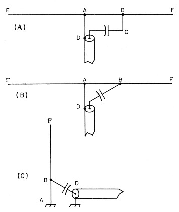
Fig. 1. The gamma-matched radiator and its family relationship to the shunt-excited vertical.
The gamma rod spacing is critical only at the AD end, and in broadcast practice it is usual to approach the radiator at a gradual angle. At amateur frequencies, anything from No. 12 wire(2) to tubing equal in diameter to the radiator have been used (see Handbook nomograph): and spacings at the AD end on the order of one inch at 144 Mc. to 6 inches at 14 Mc., with intermediate values for other frequencies, have worked out successfully.
Matching to feed line
When the average amateur speaks of "tuning a beam," he refers to two distinct processes. The first is that of adjusting the matching system, the gamma in this instance, to offer the proper termination to the feed line. The second is that of adjusting element lengths for maximum forward gain or front-to-back ratio. These two processes interlock to a certain degree.
The first process is carried out by tuning loop ABCD, together with appendage radiator Ele and the gamma capacitor, to provide the proper termination at the desired frequency. Among the factors which influence this are:
- Length of the gamma rod (about 7 inches for 144 Mc. to 44 inches for 14 Mc.).
- Spacing and size of the gamma rod (spacings about 1 inch for 144 Mc. to 6 inches for 14 Mc.).
- Gamma capacitor (about 7 pF for 144 Mc. to 100 pF for 14 Mc.).
- Radiator length (460 divided by frequency in megacycles(3)).
- Proximity of objects, including parasitic elements and their resonant lengths.
Unless one of these parameters is fixed one can get hopelessly lost, since they all interlork to varying degrees. In this method the radiator length is fixed and the others worked against it. Remember, a coil-capacitor combination can he mule to show the proper termination but is not the best radiator.
Equipment
A ratiometer (Monimatch, s.w.r. bridge, etc.) plus your transmitter, preferably low power, is all that is necessary. The simplest kind of s.w.r. meter or r.f. bridge, requiring only a few watts of power, is preferred.
The simple field-strength meter shown in Fig. 2 plus a v.o.m. with at least a 100-microampere movement is required if you want to make frontto-back adjustments. Use of a grid-dip meter as a source of r.f. voltage is unsatisfactory in this application, nor is one required at any time unless used as mentioned later.
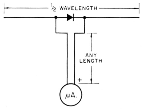
Fig. 2. Sensitive field-strength meter using crystal diode (such as a 1N34) and microammeter. The latter should have a range of about 100 microamperes full scale, and may be the meter in a volt-ohm-milliammeter if a suitable low-current range is incorporated.
Adjustment of gamma
Mount the beam on a convenient support at a height easily reached from the ground. The top of a stepladder is convenient - or even a fence post. The roof top is better but not necessary. Don't be too concerned about surrounding objects; tuning under poor circumstances is better than no tuning at all.
- Adjust the gamma to the suggested dimensions. Make the reflector 5 per cent longer than the radiator and the director 4 per cent shorter. Additional directors should be successively 4 per cent shorter.
- Install the s.w.r. meter at the transmitter end of the feed line and adjust the power output for proper operation of the meter at half sensitivity. This is done to extend the range during final adjustment. Only a few watts are required - the lower the power the better, since "hot" adjustments are to be made.(4)
- Move the s.w.r. meter to the antenna end of the feed line, placing it in such a position that the meter can be seen while making subsequent adjustments.
- Adjust the gamma rod length for minimum s.w.r. A temporary sliding shorting bar consisting of two battery clips screwed back to back is convenient. It is unlikely that this adjustment alone will produce a minimum.
- Adjust the gamma capacitor for minimum s.w.r. Alternate the adjustments between gamma rod length and gamma capacitor setting for minimum s.w.r.
- Finally, touch up by adjusting the radiator length slightly, but not more than one or two per cent. If a greater change is needed, go back to steps 4 and 5 and try another combination.
In all three of the latter steps the adjustments should allow the s.w.r. to go through a minimum and then rise again. By this time the s.w.r. reading should be so low as to make the reading unreliable on the scale being used, so shift to the most sensitive scale on the v.o.m., if one is being used, or increase the sensitivity of the meter by cutting out more resistance if a Monirhatch type is being used.
If at any time you should lose your place, or have any doubt as to the correctness of the adjustment, readjust the radiator to the calculated length and start all over. The sequence is: gamma rod, gamma capacitor, and radiator length for touching up.
Depending on size of the beam and the frequency, you may have to duck out from between or under the elements after each adjustment, if such movement results in a change in the s.w.r.
If a satisfactory minimum s.w.r. cannot be attained during any of the three latter adjustments look for:
- Radiator length too far off, preventing resonance (see below).
- Poor Q in gamma capacitor and loop system. The W2VS type of concentric capacitors has excellent Q and is preferred. Spacers should have low power factor. Plastic tape is unsatisfactory, and you will have one big mess if you use high power.
- Poor coax connections. Solder all coax to connectors. In one instance a right-angle connector showed an open circuit only when installed in a line.
- Beware of unmarked surplus short lengths of coax in connecting the ratiometer. It is better to cut a short length from the same piece used for the feed line.
- Telescoping elements not making electrical contact. Test with an ohmmeter. If there is no coating of grease on the inside at the telescoping joint, put one on and tape up the joint with plastic tape after final adjustment of length.
- Excessive harmonic content or parasitics in the r.f. source, either through mistuning, or inherent in transmitter.
- Ratiometer improperly calibrated or not working properly. Test with a noninductive resistor - not at the bridge coax terminal but at the end of the coax where it connects to the gamma.
The first mentioned item is the most frequently occurring trouble and usually accounts for freak gamma dimensions or capacitance. Check the resonant frequency by shifting the transmitter frequency 200 kc. higher and lower and observing where the minimums. w.r. occurs. If the minimum occurs at other than the desired frequency, readjust the radiator length and repeat all steps.
If none of these measures work, couple a grid-dip meter to point D in Fig. lA with the feed line off. You will find several dips; the most pronounced for the radiator, a less-pronounced one higher in frequency for the director, and another lower in frequency for the reflector. This will give you an idea as to how far off resonance you are. There have been cases where resonance occurred outside of the range of the transmitter.
Adjustment of director and reflector
The second phase of tuning will be omitted by most hams, aF formula lengths work out fairly well. Adjustment for maximum front-to-back is much easier than for forward gain because the former is quite sharply defined. Moreover, it is more dramatic when demonstrating the beam!
String up a half-wave dipole with a diode detector, using pieces of string as insulators, be tween any convenient supports that are as far away as possible while still showing a half-scale reading with the back of the beam pointed at the dipole. If these adjustments are being made on the roof top, the pick-up dipole draped over the neighbor's roof is fine; otherwise, even draped over a hedge is satisfactory.
Run a long two-conductor lead from the dipole to the beam so that effects of adjustment can be watched. It is best that the lead wire be laid on ground to preclude r.f. pick-up. Proceed as follows:
- Adjust reflector length for minimum pickup. This adjustment is very critical, a change of one half inch producing a decided change in meter reading.
- Adjust director length for minimum pickup. This adjustment is not as critical as that for the reflector.
- Increase the sensitivity of the meter or move the pick-up dipole closer (or increase power) as adjustment proceeds so that a half-scale reading is obtained at all times.
- In both (1) and (2) a minimum should occur as the proper length is passed.
- Reinstall the ratiometer in the feed line and check to see that the s.w.r. has not changed materially. If it has, readjust according to the procedure given previously, keeping the radiator length a fixed quantity except for minor touch-up.
In practice, a change of one half inch or so in element length will not be noticed at the receiving end of a contact, but it is comforting to know that it is "on the nose." Raising the beam into position does not change the s.w.r. as much as one is led to suspect, and this method is the next best to making adjustments with the antenna in its final position.
Notes
- Nose, "A Lightweight 14 Mc. Four-Element Beam," QST, Nov., 1948.
- Nose. "A Lightweight 21 Mc. Three-Element Beam," QST, April, 1954; The A.R.R.L. Antenna Bonk, p. 253.
- Different sources give Squires varying from 460 to 480. A large number of experiments tend to favor the former figure. I would like to hear about the experiences of others.
- Take due precautions, such as grounding the inner conductor of the coax through an r.f. choke, to prevent high voltage from appearing on the antenna should a blocking capacitor fail. Additionally, it is suggested that the center conductor be grounded through another r.f. choke at the antenna end.
- Reynolds, "Simple Gamma Match Construction," QST, July. 1957.
Katashi Nose, KH6IJ.