100 Watt transistor mobile power unit
500 Volts at 225 mA.
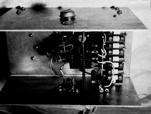
A 500 volt 225 mA transistor power supply for mobile use. The transistors are mounted on large aluminum surfaces to provide cooling. Rectifiers are silicon.
The power transistor of the type designed for switching at low frequency is ideally suited for use in mobile power supplies. However, the general lack of suitable components and design data has kept most amateurs from taking advantage of the features that supplies of this type have to offer. It is hoped that an account of some experimental work done by the author, with assistance from W9MZN, W8ZM and W8BNG, will be of interest to others who are contemplating a similar project.
The design was aimed at a transistor supply that would replace the old stand-by PE103 used to power a 50-watt mobile rig. An output of 500 volts at 225 ma. was needed. While several suitable transistor types are now on the market, the 2N278 was selected for the job. This unit is readily available. It can be obtained from United Motors dealers who service Delco receivers throughout the United States. The price, although somewhat high, is not prohibitive. The 2N278 has a maximum current rating of 12 amperes and operates from a 12-volt car-battery system.
Fig. 1 shows the circuit of the first experimental attempt. The transformer Tr was designed for a frequency of 400 cycles and was wound on a core of stacked 0.014-inch hi-nickel silicon laminations. ("Audio C" core material is also suitable.) In addition to the high-voltage secondary L3 and the 12-volt primary L2, the transformer has a split feed-back winding, Lr, of 12 to 15 volts.
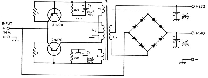
Fig. 1. Circuit of the first experimental transistor mobile power supply. Capacitors are electrolytic. Resistors are 2 watts or more, and values are in ohms. Rectifier units (8 required) are 130 volt a.c. input, 500 mA d.c. output silicon (SarkesTarzian M500). Transformer T1 is discussed in the text (Powertran P3015 or Meteor M88565). (See footnote 1).
How the circuit works
When voltage is applied to this circuit, one of the transistors will start conducting more than the other because of manufacturing differences in the two transistors. The flow of collector current through the transformer primary is in such a direction as to bias the conducting transistor into greater conduction while the other transistor is biased with the opposite polarity to cut it off. The current continues to increase until the transformer saturates. At this point a reversal of current takes place and the first transistor is cut off while the second is driven into conduction. The resistors aid in the starting of oscillation by biasing the transistors out of the nonlinear region. The output wave is essentially square as shown in Fig. 2.

Fig. 2. Oscillograph showing the input waveform of the circuit of Fig. 1 after despiking.
At the instant of reversal, a high-voltage spike is generated by the collapsing field of the transformer. Although of short duration, these spikes can cause transistor failure if their amplitude exceeds the collector diode voltage rating. C1 and C2 are used to suppress the spikes as shown in Fig. 2. The amplitude of the spike can also be limited by the use of transformer core material of relatively high residual magnetism, since with such a core the field does not collapse so abruptly when the magnetizing force is removed.
Improving efficiency
With the arrangement of Fig. 1, a full-load efficiency of 72 per cent was obtained. At the suggestion of W8ZM, attention was turned to the use of a high-permeability toroid feedback-transformer system and a hypersil power transformer. The circuit used is shown in Fig. 3. In this circuit, it is the small toroid transformer, rather than the power transformer, that saturates to provide chopper action. It is also the frequency-determining element. In this particular case, the frequency checked at 980 cycles. An efficiency of 85 per cent was obtained at a full-load output of 500 volts, 225 ma. With the better core material, no despiking network was found necessary. The network consisting of C1, R1, CR1 and CR2 is for the purpose of suppressing random transient peaks.
The circuit of Fig. 1 provides automatic protection against overload. If the supply is overloaded, the circuit simply stops oscillating. In the circuit of Fig. 3, however, feedback is more independent of the load and therefore overload protection is not automatic. Proper fusing of both input and output circuits is recommended.
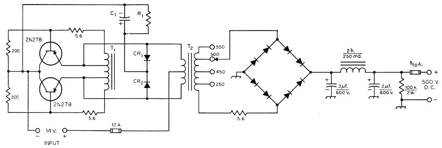
Fig. 3. Transistor power-supply circuit using a toroid feedback transformer and power transformer with hypersil core. Capacitors are electrolytic. Resistors are 2 watts and values are in ohms (K = 1000). CR1 and CR2 are 70 volt 500 mA silicon rectifiers (Sarkes-Tarzian 10M500). R1 is 150 to 500 ohms, 2 watts. C1 is a 5 to 20 µF 50 volt electrolytic. Power rectifier units (8 required) are 130 volt a.c. input, 500 mA d.c. output silicon (Sarkes-Tarzian M500). T2 is the feedback transformer. (Osborne7l 6). T2 is the 1000-cycle power transformer (Osborne 14572-1 4) (See footnote 1).
In both circuits, silicon diodes are used in the bridge rectifier to conserve space and make it unnecessary to supply rectifier filament power. These rectifiers also help to keep the efficiency up, since the drop across them is much less than with tube rectifiers. To obtain the necessary voltage rating, two diode units in series are required for each leg of the bridge. Since the rectified output on each half of the cycle is very close to a square wave, the output with full-wave rectification requires very little filtering.
The supply shown in the photograph was built by W8BNG and the transformers were designed by W8ZM. The problem of heat sink (cooling) was solved by mounting the two transistors on 9 × 10 inch walls of 1/8 inch aluminum sheet. These walls were fastened to the sides of the chassis on which the remainder of the components were mounted. In the circuit of Fig. 3, the collectors (which are connected to the outer shells of the 2N278s) are connected directly to the negative side of the battery. In systems where this negative side is grounded, the transistors may be mounted directly on the aluminum walls. Otherwise, very thin insulating material should be used between the transistors and the aluminum walls to provide electrical insulation while maintaining maximum heat conductivity.
All of those who participated in this project2 had a lot of fun and we are now looking forward toward a more compact and efficient transmitter using transistors in at least the modulator, leaving the high-voltage supply free to deliver its full output to the r.f. section.
Notes
- The transformers mentioned in the text may be obtained from the following addresses;
Powertran Corp., 26320 W. 7 Mile Rd., Detroit 19, Mich. Meteor Transformer Mfg. Co., 8877 Hubbell, Detroit 28, Mich.
Osborne Transformer Corp., 948 East Lafayette Ave., Detroit 7, Mich. - It is interesting to note that the conclusions drawn from this independent investigation of transistor-type mobile supplies closely parallel those of the work done by W1YOR described in the April issue. - Ed.
Robert L. Karl, W8QFH.