Pi-network tank design
The method of presenting pi-network tankcircuit design information used in the accompanying charts is due to D. W. Wulf, W9FID, Mendota, Ill. These graphs contain the same intrinsic information as those currently in the Handbook,' but give it in terms of inductance and capacitance, rather than reactance. The values shown apply at a frequency of 3.5 Mc. and must be modified appropriately for other frequencies. Average values for the various amateur bands can be found as follows:
| 3.5 Mc. | Use as given. |
| 7 Mc. | Divide L and C values by 2. |
| 14 Mc. | Divide L and C values by 4. |
| 21 Mc. | Divide L and C values by 6. |
| 28 Mc. | Divide L and C values by 8. |
An approximate value for the plate load resistance can be found from
![]()
It is generally satisfactory to use a single value of tank inductance for an entire band, provided the loading capacitor C2 can be adjusted over a fairly wide range. When using a fixed tank inductance calculated as described above it is advisable to select a Q of at least 15, since the operating Q will decrease with increasing frequency in the band.
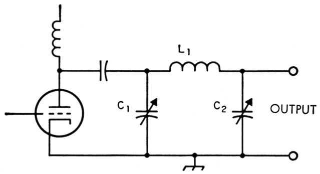
Fig. 1. Pi-network tank circuit, with component designations used in the charts. The plate load resistance is the resistance looking into the left-hand side of the network when an actual load is connected to the' output" terminals.
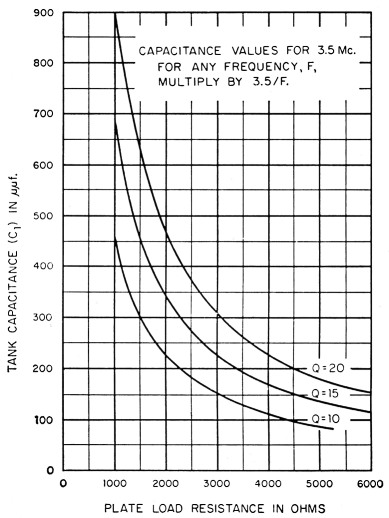
Fig. 2. Tank capacitance as a function of plate load resistance. The tank capacitance is dependent only on the tank Q, so this chart applies regardless of the value of the actual load resistance.
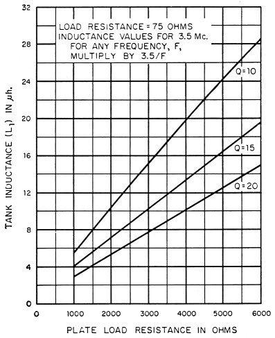
Fig. 3. Tank inductance as a function of plate load resistance, for an actual load of 75 ohms.
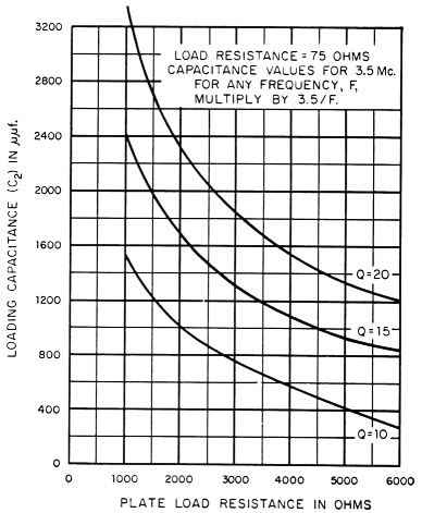
Fig. 4. Output or loading capacitance as a function of plate load resistance, for an actual load of 75 ohms.
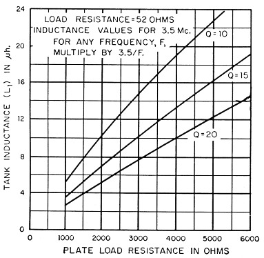
Fig. 5. Tank inductance as a function of plate load resistance, for an actual load of 52 ohms.
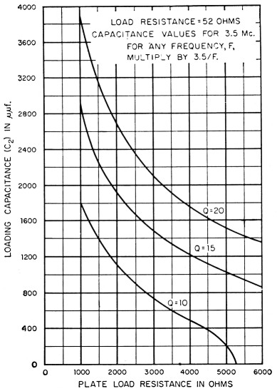
Fig. 6. Output or loading capacitance as a function of plate load resistance, for an actual load of 52 ohms.
Notes
- Pi and Pi-L design curves, QST November 1955, page 28.