Four band dipole with traps
Design for the 7- to 28 Mc bands.
Since the introduction of the traptype multiband dipole by W3DZZ, a few years ago, interest has been divided about equally between his arrangement and the parallel-dipole system. While the latter has some mechanical disadvantage, it can easily be made to fit a smaller space when necessary simply by sacrificing the dipole for the lowest-frequency hand. If a similar reduction of the trap antenna is wanted, the system must be redesigned. This article shows how to do it.
The four-band antenna system described herein may be of interest to the ham who wishes to work on several bands but does not have sufficient space for a dipole equipped with traps for five-band operation. Unlike the five-band system,(1),(2) which requires more than 100 feet, this multiband trap antenna spans less than 60 feet. Low standing-wave ratios on 10, 15, 20 and 40 meters are obtained.
The purpose of the resonant traps is probably well known but will hear repeating. The traps are constructed to be resonant at the desired operating frequency in the 2O meter band - in this case, 14.1 Mc. The "inner" sections, A, as indicated in Fig. 1, form a dipole which is also resonant at 14.1 Mc. The "outer" sections, B, are effectively isolated (at this frequency) by the traps.
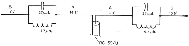
Fig. 1. Sketch showing dimensions of a trap dipole covering the 40 through 10 meter bands.
When operating in the 4O-meter band, the capacitive reactance of the traps increases and the inductive reactance decreases. The net effect is that the traps act as inductors between sections A and B, permitting the entire antenna to resonate as a loaded 40-meter dipole.
When either the 21 Mc. or 28 Mc. band is used, the inductive reactance increases and the capacitive reactance decreases. The traps then act as capacitors between sections A and B. The antenna becomes a 3/2 λ harmonic radiator on the 15 meter band and 5/2 λ on the 10 meter band.
The dimensions shown in Fig. 1 are for halfwave resonance at 7.2 Mc and 14.1 Mc and for harmonic resonance at approximately 21.2 Mc and 28.2 Mc. Since each trap is 4 inches long, the over-all antenna length is 55 feet. In this case, the dimensions of sections A came out very close to the figure of 16 feet 7 inches obtained from the formula for the average length of a 14 Mc dipole. This indicates that the traps do, in fact, isolate sections B at the trap frequency.
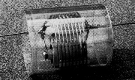
The 14 Mc trap is enclosed in a weatherproof cover made of plastic sheet. The ceramic capacitor and strain insulator are inside the coil.
Values of L and C
The choice of L and C is simple if only the 20-meter and 40-meter bands are considered, since sections B can readily be cut to produce 40 meter antenna resonance for any reasonable combination of L and C which is resonant at 20 meters. However, sections B should also produce 15 and 10 meter resonances with the same traps. The trick, therefore, is to arrive at an LC combination and a length B which meets all these requirements.
Construction
As shown in the photograph, each trap is literally built around an "egg" or "strain" insulator. In this type of insulator, the hole at one end is at right angles to the hole at the other end, and the wires are fastened as in Fig. 2. These insulators have greater compressive strength than tensile strength and will not permit the antenna to fall should the insulator break, since the two inter-looped wires prevent it. There is ample space within the inductor for both the insulator and capacitor. The plastic covers are not essential but are considered desirable because they provide mechanical protection and prevent the accumulation of ice or soot and tars which may not wash off the traps when it rains.
Electrically, each trap consists of a 25 pF capacitor shunted by 4.7 µH of inductance. Centralab ceramic transmitting capacitors 85725Z, rated at 15,000 volts d.c., were available and used since they will safely handle a kilowatt. Undoubtedly other similar capacitors rated at approximately 6000 volts would be satisfactory, as well as cheaper. The inductors are made of No. 12 wire, 2½ inches in diameter, 6 turns per inch (B & W 3905-1 coil stock).
One may wish to choose a different frequency in the 20 meter band for which optimum results are desired; for example, 14.05 Mc for c.w. operation, 14.25 Mc for phone operation, or perhaps 14.175 Mc for general coverage. The author's choice was 14.1 Mc. In any case, the number of inductor turns is adjusted accordingly.
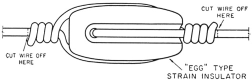
Fig. 2. Method of connecting the antenna wire to the strain insulator. The antenna wire is cut off close to the wrap before checking the resonant frequency of the trap.
Trap adjustment
As a preliminary step, loops of No. 12 wire are fitted to one of the egg insulators in the normal manner (see Fig. 2), except that after the wraps are made, the end leads are snipped off close to the wraps. A capacitor is then placed in position and bridged with short leads across the insulator and soldered sufficiently to provide temporary support. The combination is then slipped inside about 10 turns of the inductor, one end of which should be soldered to an insulator-capacitor lead. Adjustment to the resonant frequency can now proceed, using a grid-dip meter.
Coupling between the g.d o and the trap should be very loose. To insure accuracy, the station receiver should be used to check the g.d.o frequency The inductance should be reduced ¼ turn at a time. If one is careful, the resonant frequency can easily be set to within a few kilocycles of the chosen figure.
The reason for snipping the end leads close to the wraps and the inclusion of the loops through the egg insulator soon becomes apparent. The resonant frequency of the capacitor and inductor alone is reduced about 20 kc per inch of end lead length and about 350 kc. by the insulator loops. The latter add approximately 2 pF to the fixed capacitor value and account for the total of 27 pF shown in Fig. 1.
Assembly
Having determined the exact number of inductor turns, the trap is taken apart and reassembled with leads of any convenient length. One may, of course, connect the entire lengths of sections A and B to the trap at this time, if desired. But, if more convenient, a foot or two of wire can be fastened and the remaining lengths soldered on just before the antenna is raised.
The protective covers are most readily formed by wrapping two turns (plus an overlap of inch) of 0.020 inch polystyrene or lucite sheeting around a 3 inch plastic disk held at the center of the cylinder so formed. The length of the cover should be about 4 inches. A very small amount of plastic solvent (a cohesive cement that actually softens the plastic surfaces) should then be applied under the edge of the overlap and the joint held firmly for about two minutes to insure a strong, tight seal. The disk is pushed out and the inner seam of the sheeting sealed.
The trap is then placed in the plastic cylinder and the end disks marked where the antenna wires are to pass through. After drilling these holes, the disks are slipped over the leads, pressed into the ends of the cylinder and a small amount of solvent applied to the periphery to obtain a good seal. Some air can flow in and out of the trap through the antenna-wire holes, and this will prevent the accumulation of condensation.
Length Adjustment
It is well known that s.w. ratios are not uniform throughout the band or bands for which an antenna is designed. In a trap antenna, the choice of frequencies for best performance is a compromise. After making the traps resonant at 14.1 Mc, sections A were adjusted for resonance. Sections B were then adjusted for resonance at approximately 7.2 Mc and simultaneous readings were taken in the 10 and 15 meter bands. For the dimensions shown, with the antenna about 250 ft above street level and 35 ft. above electrical ground, the author obtained an s.w.r. of virtually 1 to 1 at 7 2 Mc, with maximums of 1.3 and 1.1 at 7.0 and 7.3 Mc., respectively. In the 20 meter band, the s.w.r. was also 1 to 1 at 14.1 Mc, 1.1 at 14.0 Mc and 1.3 at 14.3 Mc In the 15-meter band, the values show the effect of dimensions favoring best operation on the other three bands. However, they are quite satisfactory - 1.9 to 1 at 21.15 Mc, with maximums of 2 at 21.0 Mc, and 2.2 at 21.4 Mc. In the 10 meter band, the s.w r was 1.3 to 1 at 28.0 Mc, 1.1 at 28.4 Mc, 1.5 at 29 Mc, and only 2.4 at the upper extreme of the band.
RG-59/U 73 ohm coaxial cable forms the transmission line and is connected to the antenna through a Continental Electronics & Sound Co. "Dipole Dri-Fit Connector." After connecting the cable and antenna wires, the connector was coated with several layers of insulating varnish to make certain that the junction was watertight.
For those who prefer to operate mostly in the phone portions of each band, optimum performance will be obtained with somewhat different dimensions than shown in Fig. 1. The traps should be resonant at approximately 14.25 Mc. Each section A probably will be about 2 inches shorter, since the resonant frequency changes about 65 kc. for an inch of change in A. Dimension B is, of course, affected by any change in section A as well as the loading effect of the traps. For resonance at 7.25 Mc and 14.25 Mc, sections A and B will measure about 16 feet 6 inches and 10 feet 6 inches, respectively. To arrive at the correct lengths, s.w.r. measurements should be taken in the 10 and 15 meter bands, in addition to those made in the 20- and 40-meter bands, since at the higher frequencies antenna resonance varies rapidly with changes in length.
The antenna should be resonant, independently of the transmission line, at the desired frequencies. Since the impedance of the antenna, at resonance, depends on height, proximity to nearby conductors, and other factors, it is wrong to assume that the antenna and feedline impedances are matched. Usually, they are not.
To enable one to "look" at the antenna separately while it is in its working position, the length of the transmission line should be adjusted to a halfwave length or some multiple thereof. This length can be determined, if coaxial cable is used, by shorting the feedline at its junction with the antenna and (using a grid dipper loosely coupled to a small link across the station end of the cable) varying its length until a dip occurs at the chosen trap frequency. Here, as berore, the station receiver should be used to check the grid-dipper frequency.
The transmission line is then reconnected to the antenna and transmitter and dimensions A varied until a minimum s.w.r. (which will be very nearly 1 to 1) is obtained at the trap frequency. The antenna is then resonant at this frequency. Dimension B is similarly found for the desired frequencies in the 40, 15 and 10 meter bands.
In the determination of exact antenna length, the usual method is to start with too much wire and observe the effect on the resonant frequency as the wire is pruned. Where two sections (A and B) are involved, as here, one may wish to see the effect of undercutting one section, varying the length of the other, and so on. To simplify this procedure, it is suggested that several 2-inch links of wire be prepared so the antenna can readily be lengthened or shortened. If the ends of the links are given rather sharp bends and crimped when put together, the resulting hook joints are strong enough to support the experimental antenna safely. After final dimensions are decided upon, the links and piece-out sections are replaced with unbroken lengths and the completed antenna pulled up to its working position.
It might be mentioned here that the antenna erected by the author is made of enameled wire. After the wires at the free ends of sections B were looped through the supporting egg insulators, the wraps were soldered. This was done so that the electrical length would be the same if others chose to use bare wire.
The antenna described is sufficiently broad to give very acceptable results on all four bands. With low s.w. ratios, one has the satisfaction of knowing that most of the transmitted power is placed where it belongs - in the antenna. The time and effort put into its construction should be quite rewarding to the ham who must compete with beams and rhombics.
Notes
- Buchanan, "The multimatch antenna aystem," QST, March, 1955.
- Greenberg, "Simple trap construction for the multiband antenna," QST, October, 1956.
David P. Shafer, K2GU.