New thresholds in V.H.F. and U.H.F. reception; Devices and diodes
In december QST(1) it Was shown that, because of cosmic noise relationships, a reduction in receiver noise figure can result in quite large improvements in over-all sensitivity in the u.h.f. bands. In fact, it was determined that sensitivity at these frequencies can far exceed that obtained on two meters if one can approach an ideal receiver. If the previous article sold everyone on the idea that something worthwhile may be gained, then it is time to take a look at the devices that can accomplish this.
It might be well to first run through a qualitative discussion of the whys and wherefores of the newer low noise gadgets, leaving the gory details for a subsequent article. The lion's share will be devoted to reactance devices, as these seem most applicable for amateur use. Included will be a rundown of the various configurations that are possible - or impossible, as the case may be - and of the one critical component involved: the diode. This last item is of considerable interest to us, for if reactance devices are to find widespread use among amateurs they must be feasible with diodes of reasonable availability - and price! Tubes and mixer crystals will not be covered, as they should be old hat by this time.
Maser
The word maser stands for "microwave amplification by stimulated emission of radiation" (whatever that means). A brief, and perhaps oversimplified, explanation of maser action might be to visualize a situation in which an electron in a gas can exist, possessing either high or low energy, but no energy values in between. Consider a large number of such electrons, some with high and some with low energy, and expose them to a weak microwave signal which we are attempting to amplify. It will be found that the presence of the signal will "trigger" the electrons and cause many of them to change state, the low-energy ones picking up energy, and the high-energy ones losing energy. The net result will be essentially zero, because the energy given off will be just about offset by that picked up. All that comes out will be what is left over from the input signal, unamplified.
However, if all the electrons are in the high-energy state when the weak triggering signal is applied, the electrons can go in only one direction - lower in energy. Net energy is given up (controlled by the weak input signal), and appears in the output as an amplified signal - just what was wanted. How do the electrons get into the high energy state to begin with? Simply by the application of a continuous high-power signal which forces them there. This signal is called the "pump" and, if continuously applied, will return the electrons to the high-energy state each time they are triggered down. Thus, it is the pump which supplies the power for the amplification process, much as a d.c. source supplies it for tube amplifiers.
What, then, are the drawbacks involved in the maser? In order to obtain the required electron behavior, it is necessary for the device not only to be in a strong magnetic field, but its electrons must be those within certain gases, or substances such as ruby or garnet. This could get expensive. Perhaps the most discouraging thing, however, is that to obtain low-noise operation with the maser, it must be cooled to very low temperatures by liquid nitrogen, a commodity not found in many hamshacks!
Traveling-wave tube
Another device finding application in the field of low-noise amplification is the traveling-wave tube or t.w.t. Oversimplifying again, it may be considered to consist of a focused beam of electrons traveling down a space surrounded by an r.f. transmission line whose velocity of propagation is slowed to about the same speed as that of the electrons. A weak signal put into this transmission line at the cathode end will modulate the electron beam, the amount of modulation "piling up" and becoming greater the longer the beam and the wave travel together. At the end of the tube, the beam is well modulated and r.f. may be extracted from it at a fairly high level - amplified. Since it is a high-vacuum beam tube, it is not likely to find wide amateur use until it appears on the surplus market. However, it could be very useful, as it will provide an easy 30 dB gain over a 2:1 frequency range without tuning. High-level t.w.t.'s can give 1 kW c.w. output with no strain.
A close cousin of the t.w.t. is the backward-wave amplifier. It is similar, except that the amplified output is taken from the input end. You figure that one out!
Reactance devices
Finally, we come to the particular devices which appear to hold the most promise for amateur use. Reactance devices are known by a variety of aliases, some of the more common being "mavar" and "parametric amplifier." Throughout this discussion, "reactance device" will be used as a general term - it is probably a little more indicative of how they operate. The term mavar (microwave amplification by variable reactance) is not entirely appropriate for v.h.f. application, and who knows what "parametric" means?
Actually, there is already a rather large family of the devices, some members of which function as frequency converters and others as amplifiers. There are two simple analogies which can be used in a general way to demonstrate their operation. First, consider a simple tuned circuit, such as is shown in Fig. 1. If a weak r.f. signal is present in the circuit, and the plates of the capacitor are pulled apart each time the signal reaches a peak, and pushed together each time the voltage goes through zero, the weak signal will be boosted on each cycle and come out amplified. It is evident that the source doing the pushing and pulling on the capacitor plates must do so at twice the signal frequency and that it is supplying the additional energy which appears in the tank. It expends energy moving the plates when they are charged (at time of peak signal voltage), but does not regain any energy as the plates are pushed together at a time of zero charge.
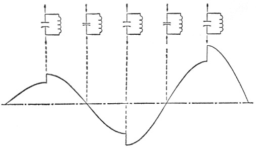
Fig. 1. Amplifier analogy of a pumped circuit. As the capacitor plates are alternately moved apart and toward each other by the pumping frequency, increments of energy are added to the signal as shown by the curve.
It will also be evident to the discerning that, if the pumping voltage occurs out of phase, the signal will be kicked down on each cycle and de-amplified - this we scarcely need! Is there, then, a phase problem and must the pump be properly synchronized with the signal? Fortunately, the answer is no. In the practical versions, this phase problem does not arise.
If the above analogy didn't put it across, let's try a simpler but less rigorous one. It consists simply of a variable air capacitor through which is passing a continuous r.f. current. When the plates are fully closed, a large current will be passed. When they are fully open, a small current is passed. If the rotor is now varied between these two values (driven by a weak input signal), it is evident that the current flowing will be amplitude-modulated at the frequency of the capacitor variation - see Fig. 2. Assuming that the rotor is essentially frictionless, then no energy is required to control the large current and we have obtained power gain and frequency conversion of the rotor-driving signal.
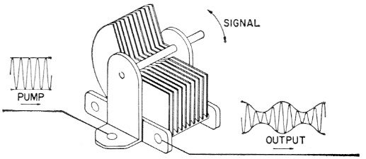
Fig. 2. Rotating capacitor analogy of the up-converter. Rotation at signal frequency varies the reactance of the capacitor and causes the pump frequency to be modulated.
It is of interest to draw a similar analogy for an ordinary crystal mixer. It would be represented not as a variable capacitor passing a large r.f. current, but rather as a rheostat. When varied, it, too, would modulate the large signal (local oscillator) at the small signal rate but, by its very nature, would be a lossy device and thus could not be expected to provide gain - and it doesn't.
Hence, it appears that potentially we have the type of device desired - one which gives gain - if we can but provide a component similar to the air capacitor above, but whose capacitance can be varied at a radio frequency rate. Under proper operating conditions, a semiconductor diode fulfills this requirement.
The critical component
Common diodes are composed of silicon or germanium in either a point-contact or junction configuration. The junction diodes merit soma") special attention since they appear to be more useful (as well as being simpler to explain).
Both silicon and germanium can exist in two separate forms, p-type and n-type. The p-type contains free positive charges, while the n-type contains free negative charges. If a lump of p-type is joined tightly to a lump of n-type, we have a junction diode. Application of negative voltage to the "n" side and positive to the "p" side will repel the free charges from the diode terminals and cause them to move toward the junction boundary. This effects a net exchange of charge, i.e., forward conduction. If the applied voltages are reversed, the free charges will be drawn away from the junction boundary, leaving a neutral region (called the depletion layer) and no net exchange of charge is possible; hence, high back-resistance.
It is this condition of back bias that is of interest. The depletion layer can be considered to be a dielectric (it has no free charges), and the regions outside it to be conductors (they contain free charges). These two regions each side of the depletion layer act as the plates of a capacitor - a capacitor whose plate-spacing and, hence, capacitance, is dependent upon applied back-voltage. Fig. 3 shows the depletion layer spacing for two conditions of back bias - low voltage for narrow spacing and high capacitance, and high voltage for wide spacing and low capacitance.
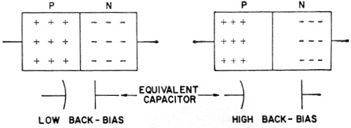
Fig. 3. Diode capacitor behavior. A change in back-bias voltage changes the width of the depletion region, effectively changing the spacing between the two groups of charges that form the "plates" of the capacitor.
Frequency converters
For our purposes, the reactance devices can be broadly classified as up-converters, down-converters, and amplifiers. Frequency converters will be discussed first because, as will be seen, even the amplifying arrangements generate additional frequencies by conversion processes. Frequency relations and "idealized" gains for up-converters are shown in Figs. 4A and 4B, and for down-converters in Figs. 4C and 4D. The term "idealized" has been applied to the gain equations for two reasons. Actually, the gain (or loss) may be almost anything depending on operating conditions. Also, the minus signs for the "gains" in Figs. 4B and 4D indicate that the configuration is regenerative. For these cases, very high regenerative gains may be obtained, but accompanied by narrow bandwidth and instability.
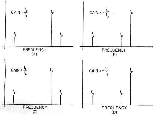
Fig. 4. Frequency relationships in up- and down-converters. The signal frequency is fs, pump frequency is fp and output frequency is fo.
The electrical circuits are fairly simple. Fig. 5 shows the basic elements for a generalized circuit applicable to amplification or conversion. The three tanks are tuned to the signal frequency, fs, the output frequency, fo, and the pump frequency, fp. The frequency fp is supplied from an external pump oscillator. In case you are wondering about the peculiar-looking capacitor which tunes the pump tank, it is just the back-biased crystal diode discussed above. The circuitry for introducing bias is omitted in the interests of simplicity.
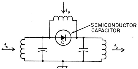
Fig. 5. Generalized two-tank circuit.
Now let's see what happens when this diode is pumped at fp and operated as an up-converter. Assume for the moment that the signal-frequency tank circuit in Fig. 5 is tuned to 100 Mc, and that the pump and output tanks are tuned to 260 and 360 Mc., respectively. When power is applied to the pump tank, the diode capacitance will vary at the pump frequency rate around the capacitance value associated with the particular value of reverse bias voltage which has been applied. The effect of the varying capacitance is to permit some of the pump power to be released to the signal and output tanks. For this example, this pump energy is most effectively utilized in converting an applied 100 Mc signal to a higher-power replica of the signal at a frequency of 360 Mc. The frequency relations for this example are shown in Fig. 4A.
Except for two important differences, the conversion process is similar to that which occurs when the diode is operated as an ordinary crystal diode mixer. In the first place, a pure reactance generates no thermal noise, and to the extent that the diode is a pure capacitance it can contribute no noise. However, an ordinary crystal mixer generates thermal noise and additional noise from shot-current effects. Secondly, when operated as a variable capacitance, a power gain can be realized, while the conventional crystal mixer dissipates both signal and injection power. The output power from such a mixer is always less than the signal input power.
Amplifiers
Fig. 6 shows one of the ways in which straight-through amplification can be achieved. There the circuit of Fig. 5 has been "folded over" and one tank now serves for both the input and output frequencies. The frequency relations for this configuration are shown in Fig. 7, along with a selectivity curve for the single tank. With this arrangement, which is based on having the pump frequency approximately equal to twice the signal frequency, an amplified version of the signal at fs, and a difference frequency, fo, equal to fp - fa, appear in this tank. Thus, the circuit is functioning simultaneously as an amplifier or converter, depending on whether fs or fo is utilized. If the circuit is working properly with reasonable gain, each input signal, fs, has a "twin brother" at fo having approximately the same strength. This could result in some confusion (and interference) when the band is wide open, since both fa and fo appear at the output terminals.
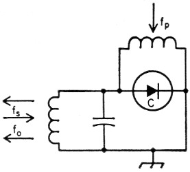
Fig. 6. The single-tank amplifier.
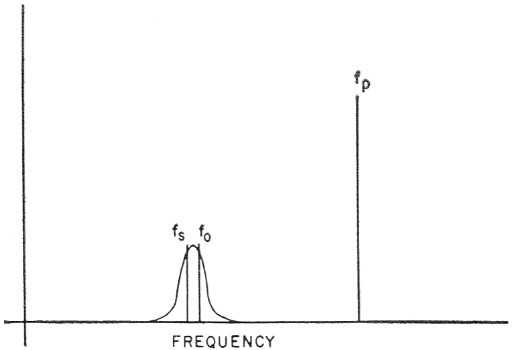
Fig. 7. Frequency relationships in the single-tank amplifier.
This and other problems associated with the single-tank amplifier can be resolved by moving fp, to a considerably higher frequency. This also moves the bothersome twin, fo, higher. Unfortunately, however, the circuit will not provide gain when operated in this condition until a resting place has been found for the "twin." This is provided by simply inserting in the circuit of Fig. 6 a tank (tuned to feo, in which fo, can be dumped and rendered harmless. Since fo and its tank serve no useful purpose except to allow the circuit to work, the nomenclature "idler frequency," A, and "idler tank" appear appropriate. See Fig. 8. The frequency relations for this circuit are shown in Fig. 9. Note that the resulting circuit of Fig. 8 is identical electrically to that of Fig. 5. However, its method of operation is fundamentally different - but this is a matter which can be dealt with later.
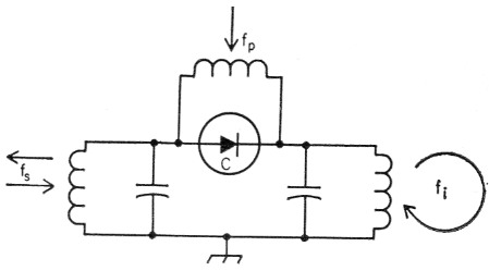
Fig. 8. The two-tank amplifier.
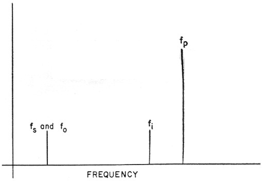
Fig. 9. Frequency relationships in the two-tank amplifier.
Up to now, the discussion has been along qualitative lines, intended to provide background for a more rigorous and detailed article to follow, covering both circuits and diodes. Much of the material presented above has been derived from the two papers(2),(3) referenced below. These should provide an adequate supply of homework for those who might be so inclined and can't wait for the next installment.
Notes
- Bateman and Bain, "New thresholds in V.H.F. and U.H.F. reception; Devices and diodes - The world below KTB" QST, Dec. 1958.
- H. Heffner and G. Wade, "Gain, bandwidth, and noise characteristics of the variable parameter amplifier," Journal of Applied Physics, Vol. 29, No. 9, September, 1958.
- A. Uhlir, Jr., "The Potential of Semiconductor Diodes in High-Frequency Communications," Proc. IRE, Vol. 46, No. 6, June, 1958.
Ross Bateman, W4AO
Walter F. Bain, W4LTU.