Operating the PL-172 in grounded grid
Practical pointers on amplifier design and use.
Because the design of the r.f. circuits is generally the thing that catches the most interest, many amplifier descriptions leave such things as power-supply details as a "problem for the student." And such details often are a problem. So are many of the other points touched on in this article describing a Class AB1 kilowatt linear.
We had a nice new s.s.b. exciter (Hallicrafters HT-32) and had made a few contacts, but were invariably snowed under by the full-gallon rigs that are now fairly commonplace. This led to thoughts about linear amplifiers. But we wanted to avoid the problems associated with swamping devices, so some form of grounded-grid circuit requiring driving power of the same order as the output of the HT-32 was indicated. At about this time the March, 1958 issue of QST arrived, and we studied the possibilities offered by the rigs built by W9KPD and W2DP,1 in which the new Penta PL-172 was employed. This jug offered 1-kw. plate dissipation with operation at relatively low plate voltage, which fitted our one-and-only high-voltage power supply. And so we started to work, lining up the required component parts, at the same time designing a chassis-housing for assembling them.
The Tube
When contemplating the component parts for any piece of electronic gear, the tube is the key to most of the other items required. The heater of the PL-172 is rated at 6.0 volts, not 6.3. Since only 6.3-volt transformers are available, some means of controlling and measuring the voltage had to be included in the design.
The cathode of the PL-172 is not connected to the heater but the two are pretty closely associated, and it became apparent that with the cathode isolated from ground the heater would require similar treatment.
As a Class AB1 linear amplifier with 200 volt on the plate and 500 volt on the screen the tube requires about 110 volt of negative bias. We wanted the voltage to be adjustable, yet reasonably well regulated, and guessed that a 15-volt range of bias adjustment would be satisfactory. The actual bias is the sum of the drops across an 0B2 voltage-regulator tube and a series resistor (R1 in Fig. 3) the latter being adjusted to provide the exact required bias.
The screen of the PL-172 is rated to take an average current of less than 50 milliampere, under excitation. Since tetrode and pentode power amplifiers are far more sensitive to variations in screen voltage than plate voltage, we needed a source of adjustable and regulated screen voltage, capable of up to 100 mA or so peak current, at a maximum of 500 volt.
The suppressor grid of the PL-172 may be operated either at ground potential or with a 75 volt positive bias. If operated at zero volts the suppressor may simply be grounded at the socket, but if it is operated with positive bias (this, the manufacturer says, increases the overall efficiency of the tube) the r.f. impedance to ground should be 3 ohms or less. To satisfy this condition, we used a 5000 pF bypass right at the socket terminals.
The anode of the PL-172 is one of those external, multiple-fin-radiator affairs. We used a Millen type 36011, snap-on plate-cap connector, p16-inch size. A blast of air must be blown up through orifices in the special socket (PL-184) and thence through the anode radiator fins for cooling. The blower must be capable of forcing about 56 cubic feet of room-temperature air per minute through the fins to cool the anode at 1 kw dissipation. The blower specified in Fig. 1 functions very satisfactorily.
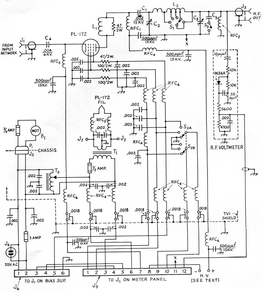
Fig. 1. Circuit diagram of the grounded-grid amplifier. Capacitances are in µF unless otherwise indicated; resistances are in ohms, resistors are half watt except as shown. Feed-through capacitors (1.8 nF) are Centralab Hi-Kap, 1000 volts; all other fixed capacitors without voltage rating indicated are 1000 volt ceramic discs, using 1 nF units in parallel as necessary; 15 kv capacitors are TV type "doorknob," Centralab TV-207.
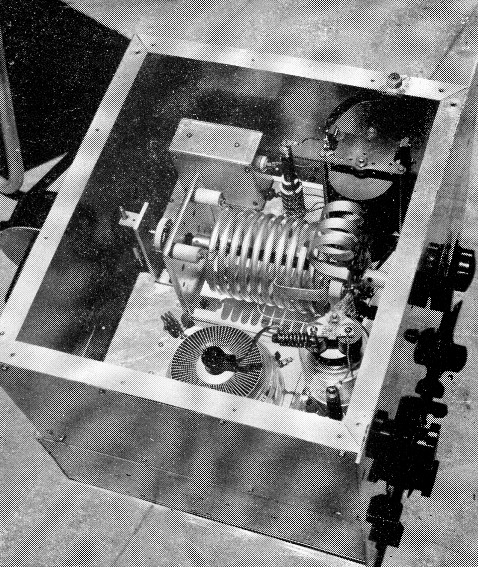
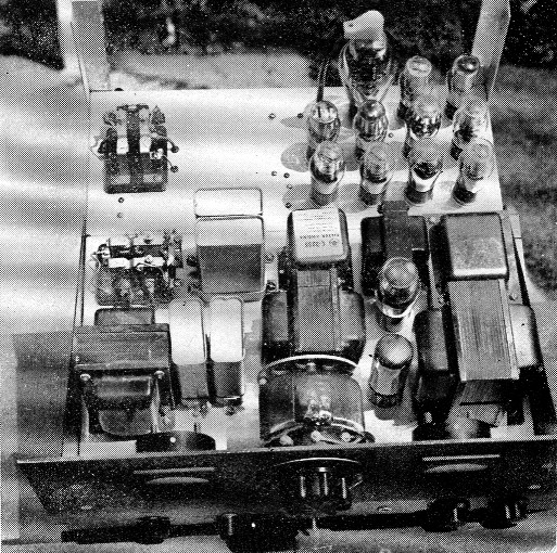
Inside the amplifier enclosure. The PL-172 anode is visible along the near wall of the enclosure, the vacuum tank capacitor is to its right, the tank coil is at about the center of the unit, and the loading capacitor is at the upper right. Two additional 500 pF units have been added to the blocking capacitor (C1, Fig. 1) since this photo was taken. The aluminum box at the upper left contains the components for the r.f. voltmeter. The ceramic capacitors near the chassis between the tube and the rear end of the tank assembly are paralleled units bypassing the suppressor grid. The blower, mounted on the rear chassis wall, is partly visible at the left.(For a view of the amplifier from the opposite side, see cover of November, 1958 QST.)
| B1 | Blower (Model 8472, No. 3, L-R Mfg. Co., Torrington, Conn.) |
| C1 | 2 nF (four 500 pF 15 kV Centralab TV-207 in parallel). |
| C2 | 400 pF vacuum variable (Jennings UCS-400). |
| C3 | 1,5 nF variable, 0.03 inch spacing (Cardwell PL-8013). |
| C4 | 4 nF ceramic, 3000 volt (four 1 nF units in parallel). |
| C5 | 1 nF ceramic, 3000 volt (for additional output capacitance on 3.5 Mc.) |
| J1,J2 | Chassis-type coax connector. |
| J3 | 2 conductor receptacle (Jones S-202-B). |
| J4 | 115 volt chassis receptacle, male. |
| J5 | 12 contact chassis-mounting connector, female (Jones S-312-AB). |
| J6 | 6 contact male chassis-mounting connector (Jones P-406-DB). |
| J7 | Tip Jack. |
| L1 | 7 turns No. 12 on 3/8 inch dia. form with 47 ohm 2 watt resistor inside. |
| L2 | Pi-network tank, with switch (B & W 852). |
| P1 | 2 conductor plug (Jones P-202-CCT). |
| RFC1,RFC2 | Transmitting r.f. choke (National R-175A). |
| RFC3 | Filament choke, dual (B & W FC-30). |
| RFC4 | 21 µH r.f. choke (Ohmite Z-28). |
| RFC5 | Transmitting r.f. choke (B & W 800). |
| RFC6 | 7 µH r.f. choke (Ohmite Z-50). |
| S1 | Part of tank coil assembly. |
| S2 | 2 circuit 3 position non shorting rotary switch. |
| S3 | Ceramic rotary ("band-switch" type). |
| T1 | Filament transformer, 6.3 V, 10 A (Stancor P-6308). |
| T2 | Adjustable-voltage transformer, 1.25 A (Superior Model 10). |
Note: Capacitances shown in diagram bypassing the screen and suppressor are in addition to capacitances built into the PL-184 socket.
The PL-184 socket
The heater, control grid and cathode of the PL-172 all connect to terminals of a 7-pin ceramic socket in the bottom of the PL-184 socket assembly. (This socket, especially designed for the PL-172, is essential for proper operation.) The screen and suppressor terminals are rings on the tube and make contact with spring contacts mounted on the body of the socket frame. The screen connection is below the chassis surface, while the suppressor is above. It is recommended that the added capacitance required to ground the suppressor for r.f. be located on the anode side of the chassis. There are also four spring clips on the top surface of the socket for holding a glass chimney (supplied as part of the socket) which guides the air-blast through the multiple-fin anode.
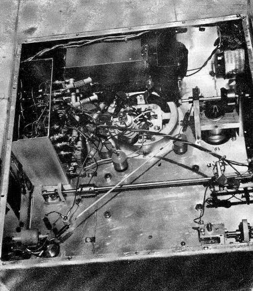
Underneath the amplifier chassis, showing bottom of tube socket and special mounting and drive for the vacuum capacitor. Along the for wall are the FC-30 heater choke, the filament transformer and, on the panel, the filament-voltage control. The TVI filters are clustered together at the upper left. The right-angle drive for the loading capacitor is at bottom right. The long shaft and associated components are not presently used.
The PL-172 is a fairly heavy tube, and since the base pins are quite small there is nothing to prevent the tube from falling out of the socket when inverted. The same thing is true of the glass chimney. When building a piece of equipment of this kind, it is our experience that the rig is upside down about half the time. Therefore, be sure to remove both the tube and the chimney before turning the chassis upside down, or risk a rather expensive alternative.
The socket includes four built-in small doorknob type high-voltage capacitors of 500 pF each. In some installations this capacitance is sufficient to make the screen cold for r.f. But we took no chance on instability, and added another 1 nF to be on the safe side.
The tank coil
The Barker & Williamson type 852 pi-network tank coil is designed for a 1500 ohm load center. We checked on the specifications for the PL-172 and estimated that this tank would be more suitable than the 851-A, and so included it in our plans. We did have to remove two turns from the 10 meter coil, and one turn each from the 15 and 20 meter sections by moving the taps. So far, we have not found it necessary to make any change in the 40 meter tap.
It takes a lot of torque to turn the band switch on this tank. We tried a couple of the commercial insulated shaft couplers, but these had crimped hubs and they slipped. So we made up a coupling from a 3-inch length of ¾ inch diameter nylon rod, drilling a ¼ inch hole through the center. Then we drilled and tapped radial holes 120 degrees apart near both ends, using ¼ by 20 Allen-type set screws. Flats were filed at the appropriate places on both the tankswitch shaft and the panel extension, and we now have a really solid coupling.
Plate tank capacitor
With 2500 volts on the plate a variable capacitor with fairly wide plate spacing is called for. And with a relatively high-C tank circuit, such a capacitor could well take on the physical dimensions of a baby-grand piano. Hence, we turned to the space-conserving vacuum variable capacitor. The Jennings type UCS-400 has about the right range (20 to 400 pF) and ample voltage rating (7500 volt). The base of this capacitor requires a special Jennings contact ring which, while excellent for electrical contact, is not in our opinion sufficiently rugged mechanically to hold the capacitor in a vertical position and withstand the torque of the drive. So we built a special mounting out of ½ by 1½ inch brass bar, as shown in Fig. 5, for the capacitor and gear drive. A gear size should be selected so that the hub of one gear can be bored out to ½ inch to fit the shaft of the Jennings capacitor. Two collars for ¼ inch shafts are required for positioning the gears and holding them in mesh. The mounting should be made secure before attempting to locate holes in the chassis for the base contact ring.
The loading capacitor
For loading adjustment we picked the Cardwell type PL-8013, which has sufficient capacitance to match a 52 ohm coax load on 80 meters with some additional padding. The spacing is ample to avoid arcing when feeding a 52 ohm load (only about 320 volts r.m.s. at 2 kw. p.e.p.). This capacitor is turned by a Millen 10012 right-angle drive working through an insulated flexible coupling and is mounted on small ceramic standoff insulators. A ½ inch hole was drilled in the chassis and fitted with a rubber grommet having a ¼ inch hole; the capacitor shaft passes through the grommet, making the hole effectively airtight. The frames of both capacitors are connected together through a heavy copper strip, and the strip is grounded to the chassis.
Metering
Although no grid current should flow in AB1 operation, one needs to know that none is flowing. Hence the 0-10 milliammeter in the grid return. And with large tetrodes and pentodes the screen current is so important that we picked a zero-center meter, fearing that the PL-172 might be one of those temperamental bottles that develops a negative screen current. However, it never has, so any ordinary 0-100 mA instrument will work just as well.
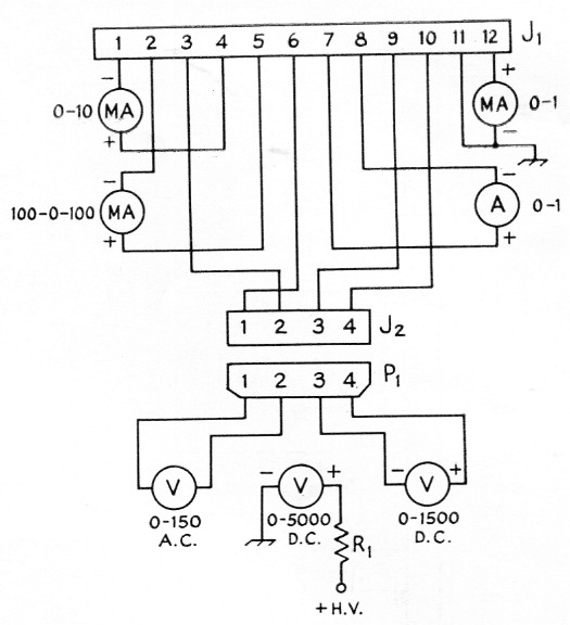
Fig. 2. Meter panel circuit diagram. R1 is the multiplier resistor for the 5000-volt d.c. meter.
| J1 | 12 contact chassis-mounting connector, female (Jones 5-312-AB). |
| J2 | 4 contact chassis-mounting connector, female (Jones 5-304-AB). |
| P1 | 4 contact plug, male (Jones P-304-CCT). |
We also considered a voltmeter, switched between screen, suppressor and control grid, to be necessary.
We elected to put the plate meter in the cathode return and thus avoid any exposed high-voltage points. Although this measures the sum of the plate and screen currents, the big part indicated is plate current. By setting the bias to provide a static cathode current at the stipulated plate current value, plus screen current, you get proper adjustment. Since the PL-172 cathode circuit should draw about 840 ma. on peaks during testing, a 0-1 ammeter is indicated.
Rectifying a sample of the r.f. output offers a sure means of checking on the accuracy of tuning. We made up a little aluminum box containing the resistors, capacitors, and the crystal diode (1N34), and connected the d.c. output, via shielded line, to a contact on the meter plug (see Fig. 1). The output meter is a 0-1 milliammeter.
An a.c. voltmeter (0-150 range) serves to measure the output voltage of T2, giving a serviceable indication, when calibrated, of the voltage applied to the heater.
The chassis
After measuring all components to be located above the chassis deck, we arrived at a size of 17 by 16 inches. Considering the shaft-centerto-bottom-edge measurement of the Groth T-3 turn-counting dial for the vacuum capacitor, a chassis depth of 6-inches appeared logical. We used aluminum stock 1/8 inch thick for the chassis; doing it again, we would use considerably lighter material.
As a means of making the chassis airtight, a bottom plate was mounted with machine screws on a ½ inch lip on the chassis. A gasket was used for sealing the chassis and plate as we were unable to make the assembly sufficiently airtight without one. Cork sheet, .030-inch thick, cut into strips ½ inch wide, works very well although any good gasketing material would do.(2)
The framework of the upper enclosure uses Reynolds do-it-yourself aluminum angles, ½ by ½ by .030 inch. The corners are held together by brass corner-angle pieces (luggage corners) bought at a local hardware store, and the sides are light (.010-inch) sheet aluminum, fastened in position by sheet-metal screws. The entire top is of perforated aluminum sheet with holes 3/16 inch in diameter, spaced on ½ inch centers. This provides plenty of exhaust area for the cooling air.
TVI-proofing, necessary on any modern transmitting equipment, involved a compartment in which all of the lines leading out of the chassis were concentrated. Every lead to the power pack and meters, and also the 115 volt a.c. and high-Voltage leads, were filtered by heavily bypassed v.h.f. chokes.
The power package
The low-voltage power package, Fig. 3, contains two separate supplies, one of which is for negative control-grid bias. This supply puts out about 220 volt d.c. at 70 mA, which is dropped to usable values through a 25K resistor, an 0B3, and R1, to provide a range of -90 to -120 volt. Relay K1 disconnects the ground for the VR tube on stand-by, causing the voltage to rise to its maximum value, about 220 volt. This is well past plate and screen current cutoff.
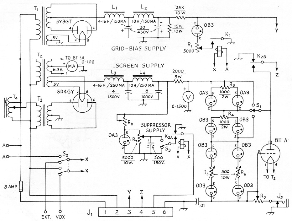
Fig. 3. Circuit of power supply for grid, screen, and suppressor. Capacitances are in µF; capacitors with polarities marked are electrolytic, others are paper. Resistances are in ohms. Numbered terminals correspond to connections in J1, Fig. 1, and terminate in a Jones P-406-DB connector.
The power package is built on two chassis, bolted together, to give enough room for the components. Component arrangement is relatively unimportant in this unit, except for weight distribution. Electrolytic capacitors and wire-wound resistors are underneath. (The vertical aluminum angle pieces at the rear corners are for helping to support the unit when it is upside down for under-chassis work.)
| J1 | 6 contact female chassis-mounting connector (Jones S-406-DB). |
| J2 | Closed-circuit phone jack. |
| K1 | S.p.s.t. relay, 115 V a.c. coil. |
| K2 | D.p.d.t. relay, 115 V a.c. coil. |
| L1 | Swinging choke, 4/16 henrys, 150 mA (Merit C-1718). |
| L2 | Smoothing choke, 10 henrys, 150 mA (Merit C-2335). |
| L3 | Swinging choke, 4/16 henrys, 250 mA (Merit C-3189). |
| L4 | Smoothing choke, 10 henrys, 250 mA (Merit C-3182). |
| R1 | 5000 ohm variable, 25 watt (Ohmite H-0162). |
| R2 | 1000 ohm 25 watt adjustable. |
| R3,R4 | 1000 ohm, 2 watts center-tapped (two 500 ohm 1 watt resistors in series). |
| R5,R6 | 500 ohm, 10 watt adjustable. |
| R7 | 5000 ohm adjustable, 10 watt. |
| R8 | 20,000 ohm 25 watt adjustable. |
| S1 | 3 position, 1 circuit rotary switch. |
| S2 | D.p.d.t. toggle. |
| S3 | S.p.d.t. toggle. |
| T1 | 470 volts c.t., 40 mA; 5 volt, 2 amp. (Stancor PC-8401). |
| T2 | Filament transformer, 5 volt, 4 amp.; 6.3 volt, 4 amp. (Merit P-3041). |
| T3 | 660 v. each side c.t., 250 mA (Merit P-3157). |
| T4 | Adjustable-voltage transformer, 3 amp. (Standard Electric Adjust-a-vou 300BU). |
Note: Terminals A-A connect to the contacts of a normally-open relay having its coil in series with the bleeder resistor in the high-voltage plate supply, as described in the text, to ensure that screen and suppressor voltages cannot be applied to the tube until the plate voltage is also applied.
The other rectifier-filter system provides up to 500 volt at 150 mA for the screen and up to 75 volt for the suppressor grid. The voltage for the suppressor is dropped through Rs, which should be set to the point where not more than 25 mA flows through the VR tube with T4 in the full voltage position. R7 is for setting the suppressor bias to exactly 75 volt.
The screen voltage is dropped slightly through a 2000 ohm resistor but the value of the voltage supplied to the parallel VR tube strings and the 811-A regulator tube is determined by the Adjusta-volt autoformer, T4, which supplies the primary of T3 with adjustable a.c. voltage. The current through the two strings of VR tubes should be balanced, and should total 52 mA. J2 is for a 0-100 milliammeter, to establish the proper balance between the currents taken by the 811-A and the VR strings. If the current is less than 50 mA through the VR tubes, they may go out on current peaks. R2 can be adjusted for optimum regulation by using the setting that results in the least screen-voltage variation when the amplifier is driven by an s.s.b. voice signal. The optimum 811-A plate current is in the vicinity of 80 ma. Relay K2 grounds both the screen and suppressor of the PL-172 on stand-by.
One position of S2 energizes Kl and K2 manually. This is necessary for testing the control grid, screen and suppressor voltages without turning on the exciter. Always test screen voltage while plate voltage is applied. In the other position of S2 the exciter VOX control turns the voltage on and off as required.
To preclude the possibility of accidentally applying screen voltage without plate voltage, a relay is connected between the cold end of the high-voltage bleeder and ground in the h.v. power supply unit (not shown). When there is no plate voltage, or insufficient voltage, the relay contacts remain open, and, since they are wired in series with the a.c. voltage actuating the two control relays in the low-voltage power package, it is impossible to go wrong. Also, the d.c. cathode return from the amplifier is not grounded in the amplifier unit, but is connected through an overload relay to ground inside the high-voltage power supply. The contacts of this relay are in series with the primary of the plate-supply transformer, and when the cathode current exceeds 900 milliamperes the whole rig goes dead. This requires a separate common ground wire between the amplifier and the high-voltage power supply chassis.
R.F. excitation
In Class ABl operation of the PL-172 the source of r.f. excitation should provide a peak voltage equal to the negative grid bias. In the initial trial of the amplifier we simply connected the output of the HT-32 to the PL-172 through a piece of RG-8 /U a couple of feet long.'It worked, of course ... that is to say, on 20 meters we were able to drive the cathode current up to about 550 mA, with 2500 volts on the plate and 500 on the screen. But we figured that this was hardly "enthusiastic" response.
The HT-32 requires a 52-ohm resistive load for full output, so not knowing what the average impedance of the PL-172 cathode input circuit might be, we wrote the manufacturer. A nice letter from W6CEM in reply pointed out that the average input impedance of the PL-172 in a grounded-grid circuit is in the neighborhood of 100 ohms, but that the exact value is a function of the cathode current, and since the plate and screen currents are variables at audio frequency it is impossible to obtain a perfect match between the exciter and amplifier at all excitation levels. He suggested either a link-coupled high-C tank circuit between cathode and ground or a properly designed pi network as a means of obtaitiing a fairly good match. He also suggested a pi-network design, so we built a "black box" rig along these lines.
After preliminary adjustment with a 150 ohm resistor as a load, the network was connected between the amplifier and the HT-32. The s.w.r. readings in the coax line from the HT-32 to the "black box" were pretty high but after some cutand-try we finally achieved a set of coils (Fig. 4) that gave something less than a 2:1 s.w.r. We have the "black box" now located immediately adjacent to the amplifier, with approximately 13 feet of 52 ohm line between it and the exciter. The average impedance of the cathode input circuit appears to be between 75 and 150 ohms (both of which terminal impedances were tried) and we now use a few inches of 150 ohm Twin-Lead between the "black box" and the amplifier. The peak r.f. voltage at the cathode of the PL-172 runs a little over 100 volts, which is sufficient to get all the law will permit out of the tube. There is never any indication of grid current, and if the exciter is pushed with too much audio the flat-topping which occurs is of course transmitted to the amplifier.
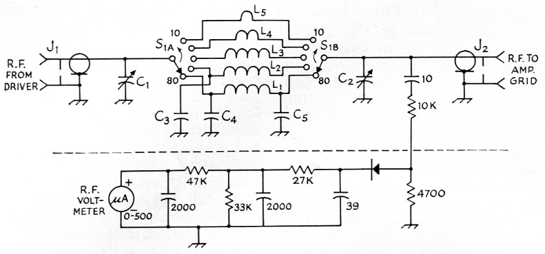
Fig. 4. Grid-input matching network. Capacitances are in pF; fixed capacitors are ceramic. Resistances are in ohm, resistors are ½ watt composition.
| C1,C2 | 1500 pF variable, 0.03-inch spacing (Cardwell Pi-8013). |
| C3 | 1 nF, 400 volt ceramic. |
| C4 | 2 nF, 400 volt ceramic. |
| C5 | 1.5 nF, 400 volt ceramic. |
| J1,J2 | Coax fittings, chassis-mounting type. |
| L1 | 13 turns No. 20, 1 inch diameter, 16 turns/in. (Air-Dux 816). |
| L2 | 8 turns No. 20, 1 inch diameter, 16 turns/in. (Air-Dux 816). |
| L3 | 4 turns No. 18, ½ inch diameter, 8 turns/in. (AirDux 408). |
| L4 | 1½ turns No. 18, ½ inch dia. (Air Dux 408). |
| L5 | 3 inch length of No. 16 wire. |
| S1 | 2 circuit, 5 position switch (Mallory L-151). |
| Band | C1 | C2 |
|---|---|---|
| 3.5 Mc | 81 | 77 |
| 7 Mc | 72 | 64 |
| 14 Mc | 41 | 33 |
| 21 Mc | 28 | 19 |
| 28 Mc | 17 | 6 |
The cathode current on c.w. or single-tone excitation can run well over 800 milliamperes. On two-tone, the cathode current can hit 750 ma. or better, and the "bow-tie" scope pattern shows nice straight sides.
This means of achieving a better impedance match between the PL-172 and an exciter with fixed output impedance is certainly well worth the time and effort put into it. Without it, the HT-32 could not fully excite the PL-172 through a coax line some 8 feet long.
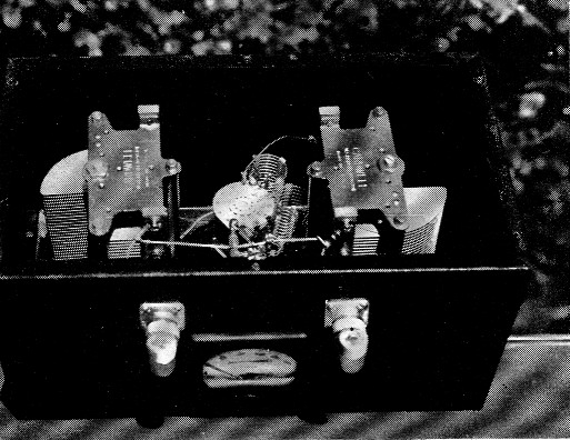
The "black box" pi-network for matching the PL-172 input impedance to a coax line. In this view it is sitting on what is normally the control panel. The meter and coax connectors are actually on the top of the assembly.
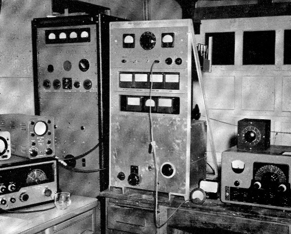
The amplifier, low-voltage power pack, and meter panels are assembled in an aluminum frame. The amplifier occupies the lower half, the meter panels are immediately above, and the power supply is at the top. The input network does not appear in this view because it is mounted close to the r.f. input connector at the rear of the amplifier.
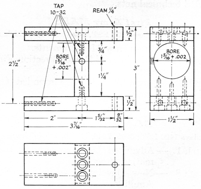
Fig. 5. Detail of vacuum capacitor mounting.
Tuning up
A suitable test setup is shown in Fig. 6. Make the line between the impedance-matching network and the amplifier really short.
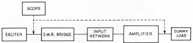
Fig. 6. Test setup. The dummy antenna can consist of nine 200 watt lamps, three parallel groups of three lamps in series. Scope may be connected to the two points indicated for checking input and output patterns.
Set the screen voltage at about 300 volt, initially, so as not to damage the screen while establishing the proper control grid voltage. Ground the suppressor to start with (later on, one can adjust R7 in the power package to give exactly +75 volt for the suppressor). Next, adjust R1 to give 110 volt negative bias on the control grid. Then reset the screen voltage to 500 volts and apply plate voltage. The static screen current should be about 9 or 10 mA and the cathode current should be about 230 mA, of which about 220 mA is plate current.
Now turn off the plate power and set the input network and amplifier plate tank to the same band. Then turn on the power and using plain c.w. excitation, gradually increase the r.f. drive until the cathode current shows about 350 mA. Resonate the plate, and watch the screen-current meter. If the meter reads over 50 mA tighten the coupling by reducing the plate-tank pi-network output capacitance (C3 in Fig. 1) and re-resonate. Repeat until the excitation is raised to maximum.
At this point you can resonate the input network. Set C1, Fig. 4, at the approximate capacitance shown under Fig. 4 and tune for resonance with C2. You will probably find that the capacitances given are not exact, and some adjustment may be required. Tune for greatest cathode current (reducing the exciter output, if necessary, to keep the tube within ratings), and you should eventually be able to reach a maximum single-tone cathode current of about 840 mA with about 43 mA of screen current and no control grid current (this assumes that the exciter is putting out its rated power). This is a plate power input of close to 2 kw., well over the legal limit, so the testing must be done with a husky dummy load.
Tuning for resonance can be done best with the r.f. output meter, but the screen meter is also a sensitive indicator. Tune for highest reading in both instances. The PL-172 when fully loaded shows very little plate current dip, and with the screen current rise superimposed on it little, if any, change in cathode current will be observed at resonance.
Those who use the HT-32 will find it easy to establish the proper conditions for a.m. Simply use enough r.f. excitation to give a cathode current of 400 milliamperes .3 This will give a carrier input of some 950 watts (at 2500 volt) and allow for 100 per cent modulation. For c.w., set the r.f. excitation to give a cathode current of 400 mA plus the screen current reading, which is about 20 mA under these conditions; therefore, we set the cathode current at 420 mA for a full "gallon" on c.w. On single sideband, depending on the characteristics of your voice and microphone, the p.e.p. may be close to 2 kW when operating at full output, but in any case the plate current should not be allowed to swing up to more than 400 mA or so on voice peaks. Better still, use a scope and hold the audio control to a point where nice full peaks show, and no flat-topping is evident.
In conclusion
The use of a special impedance-matching network in the r.f. input circuit of a linear amplifier may seem to many to be a frill. We don't admit it. You can add this "frill" with all the confidence in the world that it will improve your signal, and enable you to get more out of one of these big bottles than you can squeeze out cif a 100 watt p.e.p. fixed-load exciter in any other way.
We should add that by reducing the screen-grid voltage to about 410 volt, it is possible to operate at about 1 kw. p.e.p. input. Under these conditions, the control-grid bias should be set at 90-95 volts, or whatever it takes to make the cathode-current meter read 220 milliamperes plus the screen current. This tube should be adjusted to take about the same static cathode current regardless of the value of screen voltiage used. However, considerably less excitation voltage is required at reduced screen voltages, and grid current will probably show up on applying full excitation.
Those who might be interested in this jug for Class C plate modulation should check the recommendations of the manufacturer. The conditions outlined here are not for Class C service.
Notes
- "Two Linear Amplifiers," QST, March, 1958.
- If electrical sealing to prevent escape of TV harmonics is essential, good contact between the chassis and bottom plate can be restored by a wrap of aluminum foil around the gasket material. - Editor.
- The current will of course depend on the plate voltage used, so these figures should be considered to be approximate. Also, FCC has interpreted its power-input rule, in the case of transmitters in which the driving stage contributes power to the antenna, to mean a total of one kilowatt input to all tubes which supply power to the antenna. - Editor.
M.C. Bartlett, W9MC.