A junk-box DC volt-ohmmeter
A simple test instrument for the beginner.
Got a moderately well-stocked junk box? If it contains a reasonably sensitive d.c. meter, you have the principal comtionent of a useful test meter. The assembly described here will give you many times the value of any small parts you may have to buy to complete the circuit.
Yot; don't have to be a ham very long before you find that certain tools are required for keeping a station in working order. This doesn't mean that your equipment will be continually breaking down - at least let's hope not! -hut that there are times when you are likely to have problems. When trouble occurs you'll find that a very handy instrument to have is a icombination volt-ohmmeter. If you knew what the voltages in a piece of equipment should be - and usually the instruction manuals provide such information - checking them with your oltmeter will help in locating faults and correcting them. In other words, you can do your own service work.
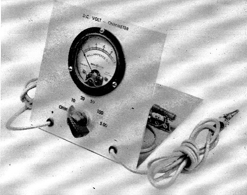
A view of the completed volt-ohmmeter. The different switch positions are labeled with Tekni-Cals.
A combination d.c. volt-ohmmeter is such a simple instrument that any Novice should be able to build one. However, it should be pointed out right now that the unit in this article is described strictly as a junk-box project. If you have to pay full price for the meter used in this instrument you'll be better off to buy a ready-built volt-ohm-milliammeter, or a kit. However, if you already own a good quality 0-1 milliammeter, or a microammeter, this test instrument should only cost a couple of dollars to construct. Also, there are plenty of meters on the surplus market that can be purchased fer a fraction of the usual price.
Before getting into construction details let's see how a voltmeter works. Fig. 1 shows the basic circuit of a d.c. voltmeter. For the purpose of explanation let's assume the meter, M, has a 0-1 milliampere movement - or, to put it another way, when one milliampere of current flows through the meter the pointer will register full scale.
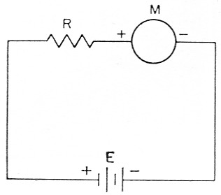
Fig. 1. D.c. voltmeter circuit.
Let's also assume that the voltage, E1 of the battery is 5 volts. Using Ohm's Law, R = E/I, if we divide five volts (E) by 0.001 ampere (I) the answer will be 5000 ohms. (Note that the current has to be expressed in amperes before it can be substituted in Ohm's Law. One milliampere equals one one-thousandth of an ampere, or 0.001 ampere.) If a 5000 ohm resistor is inserted in the circuit at R1 the meter will read full scale with five volts applied, provided the resistance of the meter itself is small - not more than 50 ohm or so.
What will the voltage be if the meter reads half scale - 0.5 milliampere or 0.0005 ampere - and the resistor is still 5000 ohm? Again using Ohm's Law, E = IR, it is found that the voltage is 2.5. If you divide the meter scale into five equal parts, each division will represent a difference of one volt, with a 5000-ohm resistor in the circuit.
Suppose you want a full-scale reading of 10 volts. With a 0-1 milliampere meter movement, R would have to be equal to 10 volts divided by 0.001 ampere, or 10,000 ohm. Now divide the meter scale into ten parts and each division will represent a difference of one volt. By now you will have observed, probably, that when you use a meter with a 0-1 mA movement you will always need 1000 ohms in series for each volt in the full-scale reading. Such an instrument is called a 1000 Ω/V voltmeter.
But suppose you have a 0-100 microammeter instead of a 0-1 milliammeter. From Ohm's Law you will find that a 50,000-ohm resistor will be required for a full-scale reading of five volts. In this case the voltmeter could be classed as a 10,000 Ω/V meter.
The important point to think about when considering the 1000 ohms versus the 10,000-ohmsper-volt meter is that the latter gives more accurate readings in high-resistance circuits. For example, suppose you want to check a circuit that has five volts applied to two 5000 ohm resistors in series. When you connect a voltmeter across one of the resistors, you would expect it to read 2.5 volt. But if the instrument is a 1000-ohms-per-volt meter with a full scale of five volts, it too will have a resistance of 5000 ohms, and since its resistance is in parallel with the 5000 ohm resistor to which it is connected, the resultant resistance is 2500 ohms.
Of course, the voltage drops across 2500 ohms and across 5000 ohms are different, although originally the voltage drops across both 5000-ohm resistors were the same. Actually, the voltmeter would read 3 of 5 volts, or 1% volts. On the other hand, if a 10,000-ohms-per-volt meter having a full scale of 5 volts were connected across the same 5000 ohm resistor, the resultant resistance would be about 4500 ohms. This voltmeter would read 2.4 volts, which is considerably closer to the true voltage.
In other words, the greater the number of ohms per volt, the more accurate the readings in high-resistance circuits. Incidentally, this is the reason why the vacuum-tube voltmeter is so useful in checking such circuits. This type of instrument usually has a resistance of at least 10 megohms, so in most cases the voltage being checked will not be affected appreciably by connecting the test instrument in the circuit. However, once you understand its limitations, a 1000 ohms per volt voltmeter is suitable enough for most amateur needs.
The Ohmmeter
In servicing a piece of equipment you'll often find it necessary to check the value of an unknown resistor or - even more common - to check continuity in a circuit. For this purpose, an ohmmeter is a very handy instrument to have in the shack. An ohmmeter is simply a low-range d.c. voltmeter provided with a source of voltage (usually dry cells) large enough to make it read full scale. In order to check a resistance, the voltmeter and battery are connected in series with the unknown resistor. The meter reading will then be less than full scale; how much less depends on the value of the unknown resistor being checked.
For example, let's assume that a 3 volt battery, a 3000 ohm resistor, and a 0-1 mA milli-ammeter are connected in series. From our previous discussion of how a voltmeter works you know that with this combination the milliammeter will read full scale. Now, suppose that a resistor of unknown value is connected in series in the circuit and the meter reads 0.5 mA, or half scale. A quick check using Ohm's Law (R = E / I) would show that 6000 ohm total resistance would be required for a reading of 0.5 mA. By simple subtraction, 3000 ohm (the known resistance) from 6000 ohm indicates that the unknown resistance is 3000 ohm. It is possible to calibrate the meter in ohms rather than milliamperes, and thus read resistance directly.
The ohmmeter part of the combination instrument described in this article can be used for measuring resistances up to about 50,000 ohm. Two 1½ volt Penlite cells are connected in series with a 0-1 milliammeter and a 3000 ohm resistor. Table I gives the approximate value of external resistance versus meter reading.
| Meter reading (mA) | Ohm |
|---|---|
| l.0 | 0 |
| .97 | 100 |
| .86 | 500 |
| .75 | 1000 |
| .60 | 2000 |
| .50 | 3000 |
| .373 | 5000 |
| .30 | 7000 |
| .23 | 10,000 |
| .20 | 12,000 |
| .14 | 18,000 |
| .10 | 27,000 |
| .06 | 47,000 |
Constructing the Unit
Before attempting construction, study Fig. 2 and the photographs to familiarize yourself with the unit. This particular instrument has voltage ranges of 10, 20, 50, 100, and 500 volt, in addition to the ohmmeter range mentioned above. A two-pole, six-position switch, Si, is used to change the various ranges by switching different combinations of resistors in series with the meter. The resistor values given in Fig. 2 are for a 0-1 mA meter. If a more sensitive meter is used the required resistance values can be found by using Ohm's Law as described earlier. Also, you may want different ranges than those used in this unit; if so, calculate the resistor values accordingly and then get a parts catalog and check on the availability of resistors of the values needed. (If necessary, resistors can be connected in series or parallel to get an exact value.) But don't plan on any voltage ranges higher than 500 volt, because this is the maximum rating of S1, and also is the maximum voltage that may be applied safely to a resistor of the type specified in Fig. 2.
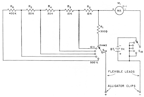
Fig. 2. Circuit diagram of the d.c. volt-ohmmeter. Resistors are ½ watt.
Voltage ranges are 10, 20, 50, 100 and 500 volt with the meter and resistance values specified. The resistors are connected in series to add up to the required value at each position of the range switch.
| BT1 | 3 volt; two 1½ volt penlite cells in series. |
| M1 | 0-1 d.c. milliammeter, low internal resistance. |
| R1 | 3000 ohm, 5 %. |
| R2 | 10,000 ohm, 5 %. |
| R3 | 10,000 ohm, 5 %. |
| R4 | 30,000 ohm, 5 %. |
| R5 | 50,000 ohm (51,000 ohm, 5 %). |
| R6 | 400,000 ohm (390,000 ohm, 5 %; 1 watt size suggested for more conservative operation). |
| S1 | 2 pole 6 position rotary (Mallory 3226J). |
Resistors are available in several different resistance tolerances, such as 10, 5, and 1 %. If you are a stickler for accuracy then by all means use 1 % resistors. However, you'll find 1 % resistors a bit more expensive than 5 % units. For most amateur work the 5 % resistors will be adequate.
The test meter shown in the photos is built on a piece of aluminum measuring 5 by 10 inches. The aluminum piece is bent at the center so that the front panel and base both measure 5 by 5 inches. However, almost any kind of box or container large enough to hold the parts can be used. In our unit, the meter and switch are mounted on the panel and all the other components are installed on the base. Two tie-point strips, one having two and the other six terminals, are used for holding the resistors.
Two 1½ volt Penlite cells are used to power the ohmmeter and these are mounted in two "broomstick" holders. These holders are available at practically any hardware or dime store, and cost 10 cents each. Connections to the cells are made by soldering leads to the end button and to the metal case. The case is negative and the button is positive.
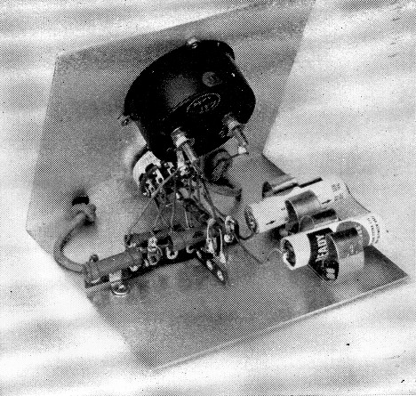
The meter and switch are mounted on the front panel and all other components on the base. Note that the two Penlite cells are mounted in "broomstick" holders.
If you purchase the switch specified in Fig. 2 you'll find that it comes with a wiring sketch to show which connections are which. However, you don't have to have a switch with six positions. If your junk-box job has fewer it only means you won't have as many ranges.
Your radio parts dealer stocks test-lead wire and you'll need about six feet of it. It is a good idea to buy three feet of red-covered wire and a like amount of black, using the red wire for the positive test lead and the black for negative. In the unit shown, the ends of the test leads that are permanently connected to the circuit are run through rubber grommets mounted on the panel. A single knot in each lead, at the back of the panel, keeps the lead from being pulled off the connection point in the course of normal use.
After the wiring is finished you can check the lowest voltmeter range by measuring the 1½ or 3 volt of the Penlite cells. A check at higher voltage can be made by measuring the voltage in a voltage-regulated circuit, such as one using a VR-105 or VR-150.
Now that you have a test meter the next question you probably are asking is, "How do I use it?" The answer to this would take quite a bit of explanation - in fact, an entire QST article. Such an article was published some time ago,(1) and it is suggested for study by anyone interested in the use of a test meter.
One last word of caution: Always make it a point to be extremely careful when working around live circuits - and by "live" we mean any circuit that has voltage on it. It may sound trite, but it is always better to be safe than sorry. Also, when using the ohmmeter for continuity checks be sure all circuit voltages are off; if the circuit is "live" you're likely to burn out the test meter.
Notes
- McCoy, "Test meters and how to use them," QST, July, 1957.
Lewis G. McCoy, W1ICP.