Working toward lower noise figures in reception at 144, 220 and 420 Mc
The projects W6AJF describes here were undertaken at a time when little or no practical information was available that would enable an amateur to build working models of these new devices. The reader, on the other hand, has the benefit of the work of Bateman and Bain, detailed in a four-part series in December, 1958, through March, 1959, QST, to help him understand what early-bird W6AJF had to find out for himself. A careful reading of the articles by W4AO and W4LTU is recommended as preparation for this one, particularly to the newcorner to the parametric-amplifier field.
Experimental parametric amplifiers
Like many other amateurs who have made a specialty of long-distance v.h.f. and u.h.f. work, the writer was extremely interested when news of the parametric, mavar or reactance amplifiers began to appear in print. But like other amateurs (and most of the professionals, too) we had only vague notions of how to put the new devices to practical use. After many hours of experimental work with a varactor diode from Microwave Associates, practical ideas began to emerge.
Many days were wasted in some of the early tests, as almost no experimental information was available. Learning about these new techniques had to be done the hard way, at the expense of much sheet metal, broken plunger-type trimmers, coax fittings and even one varactor diode. This cost of being early in a new field was well worth the effort, however, for at this writing we have one good amplifier on 144 Mc, a better one on 220 Mc, and a couple of good 432 Mc units. Further work on 432 Mc and a 1296 Mc project are planned.
Some preliminary findings
Lowest noise figures and best amplification were obtained with a varactor diode in an amplifier, rather than an up-converter. Tests were made at 144 Mc with up-conversion to 432 and 1296 Mc. The 432 and 1296 Mc, receivers had noise figures of 4 to 5 and 8 to 10 dB, respectively. This deteriorated the over-all noise figure with the up-converter, so the final result at 144 Mc was never below 2 dB. Since a noise figure of 2,5 to 3 dB was already available with several good 2-meter converters using tube amplifiers, the up-converter didn't offer much improvement. The up-converter arrangement had the added disadvantage of requiring a highly stable pump power source.
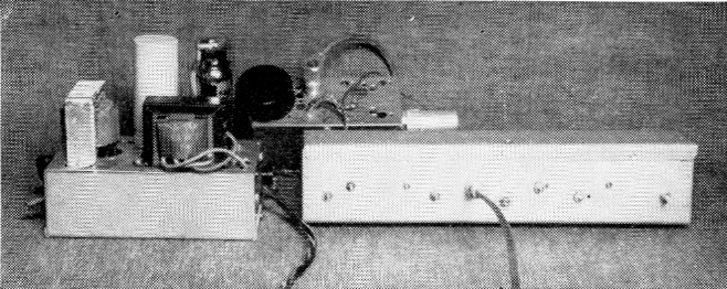
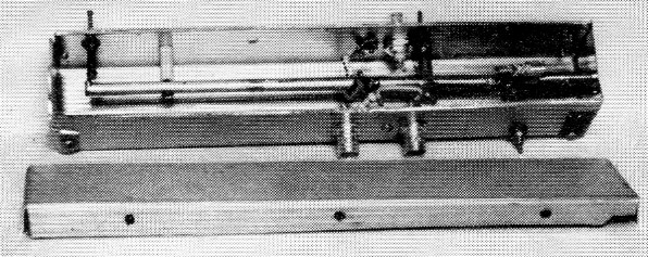
The 220 Mc parametric amplifier ready for use at W6AJF. Regulated power supply, left, is for the pump oscillator, in the small box at the rear.
On the other hand, a straight-through parametric amplifier apparently gets down under 1 dB at 144 and 220 Mc, and the pump stability requirement is not nearly so severe as with the up-converter. The up-converter is not as regenerative as the amplifier, and it seems to depend for its over-all signal gain on the extent to which the signal frequency is up-converted. A 1296 Mc receiver gives more gain from a 144 Mc up-converter than does a 432 Mc receiver and, despite the higher noise figure of the 1296 Mc receiver, the over-all noise figure is about the same.
The over-all noise figure of an up-converter system is given by
![]()
where F1 is the numerical value of up-converter noise figure, F2 is that of the receiver used as the i.f. system, and G1 is the gain of the up-converter or amplifier, as the case may be.
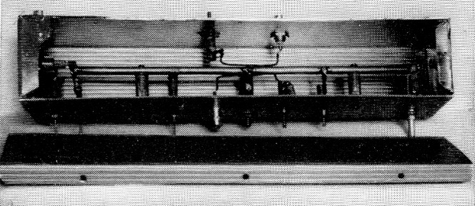
Interior of the 220 Mc amplifier, with the varactor and short pump line at the for left. Signal input and output coupling loops are the center of the line. Note that the half-wave line, used in the 220 and 432 Mc amplifiers, is mounted on insulating standoffs.
One down-converter was built, with a varactor diode and pump oscillator, but it showed a loss in gain and a poor noise figure, when compared to the up-converter system. Further up-converter tests are planned here in the near future.
One that didn't work - And why
The first parametric amplifier for 144 Mc built here used a silver-plated coaxial line, with a 3/8 inch inner conductor and a 1¾ inch outer conductor, about 12 inches long, shorted at one end. A small tuning capacitor and the varactor diode were connected from the open end of the inner conductor to the grounded shell, with a blocking capacitor in series with the diode. A variable oscillator covering 250 to 350 Mc was used as the pump, with a regulated plate supply, variable from 0 to 90 volts. The best pump frequency within the above range was around 285 Mc. Pump energy was fed in through a tap on the line about one inch from the grounded end. Coupling loops for the 144 Mc input and output were about 3 inches long, mounted close to the inner conductor and series tuned with small trimmers. Moderately good noise figure was indicated, but the unit was unstable and very difficult to maintain in operation. Because one idler frequency was close to the signal frequency the amplifier was very ineffective in the presence of auto ignition, line noise or other external interference, and the system responded to signals on the idler frequency nearly as well as to the desired ones.
These limitations seemed to eliminate as undesirable the only type of circuit that had been mentioned in amateur literature up to that time. At 432 and 1296 Mc this image effect might not be troublesome, as external noise is far lower there, and amateur QRM is not much of a problem.(1) On 144 or 220 Mc, however, on-the-air results were very disappointing, and the design was of little use, other than to gain experience.
Practical working models
Then followed a long period of paper and sheet-metal work on parametric amplifiers for 144 and 220 Mc. The idea of a cylindrical coaxial tank was abandoned, as a line built into a long box of square cross section would serve equally well and, if made with a removable side, would be much more readily worked on. The line impedance should be known for working out practical dimensions. The impedance of a cylindrical coaxial line is found from the formula
![]()
The impedance of a line built in a long box with sides equal to the diameter of a cylindrical line has an impedance 10 to 15 per cent higher. Use of a ¼ inch inner conductor in a box 2¼ inches square results in a line impedance of about 140 ohm. Boxes 12 inches long and 2¼ inches square were used in the 144 and 220 Mc amplifiers described herewith.
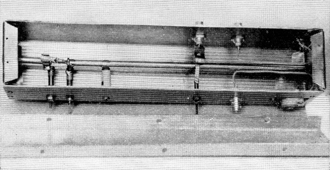
The 144 Mc amplifier uses a quarter-wave line, with the inner conductor grounded at the right end. Pump line and varactor are at the left, with signal input and output coupling at the right end.
Four frequencies are involved in the operation of the parametric amplifier: the signal frequency, the pump frequency and two idler frequencies. The idler frequencies are equal to the sum and difference of the first two. The proper value of impedance for each frequency must be present for parametric amplification with a varactor diode.(2)
A typical amateur design for 220 Mc. will be described, since the procedure outlined gave reasonably good results when applied to actual construction. A line impedance of 140 ohms was chosen, as this could be made easily with available components, as mentioned above. As a starting point a pump oscillator frequency of 500 Mc. was used. The upper idler frequency was then 500 plus 220, or 720 Mc. The lower is 500 minus 220, or 280 Mc. By a process of elimination, the coaxial line circuit shown in Fig. 2 was arrived at.
A half-wave line was chosen for 220 Mc as the two idler frequencies could be tuned more readily with this design. One or more tuning capacitors for the idler frequencies are placed across the line circuit at the grounded or zero-voltage point for 220 Mc. These reflect smaller capacitances across the open ends of the line, so only a guess can be made of the net capacitance at the end.
The Microwave Associates MA-460A varactor diode had a "zero" capacitance marking of 6.6 pF. This plus 1 to 2 pF from the small tuning capacitor gives about 8 pF at the varactor end of the line.
The inductive reactance of the short pump-frequency line, in series with the diode capacitance to ground, cancels a small portion of the diode capacitive reactance. For this reason, the pump line should be short; perhaps an inch or so for 144 or 220 Mc amplifiers. The receiver with which the amplifier is used must have enough selectivity at 220 Mc to keep any 280 or 720 Mc signals or noise from getting into the first mixer. A few slug-tuned circuits at 220 Mc should accomplish this.
In Fig. 1 is shown a curve which gives the capacitive reactance, normalized to the characteristic impedance, required for resonance at the input terminals of a short-circuited transmission line, for lengths up to about one-quarter wavelength. If an open-circuited line with equal capacitance at each end is used, the length obtained from the curve of Fig. 1 must be multiplied by a factor of 2. The wavelength in inches for any frequency can be calculated from the expression, 11800 / fmc, which gives figures of 53.5 inch for 220 Mc, 42 inch for 280 Mc, 23.6 inch for 500 Mc, and 16.4 inch for 720 Mc. For a capacitance of 8 pF at each end of the line, the value of X at 220 Mc is 84 ohm, at 280 Mc 70 ohm, at 500 Mc 40 ohm, and at 720 Mc 28 ohm. Each of these divided by 140 gives the X/Z on the vertical scale of Fig. 1. Reading the values of line length from the curve gives the length to a zero-voltage point from each end of the capacity-loaded circuit.
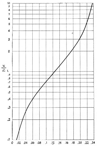
Fig. 1. Curve showing normalized input reactance (X / Z) versus length in wavelengths of short-circuited coaxial or parallel-line circuits. X is the inductive reactance of the line and Z is the characteristic impedance.
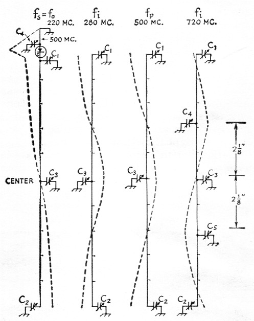
Fig. 2. Voltage distribution and tuning points on a 220 Mc line 10 inches long, with a characteristic impedance of 140 ohms. Idler frequencies of 280 and 720 Mc result from the use of a pump frequency of 500 Mc and a signal frequency of 220 Mc.
The actual values plotted in inches in Fig. 2 are obtained by multiplying the wavelength in inches for each frequency by the decimal values of Fig. 1. These were 5, 3.15, 1.0, and 0.82 inch, respectively, from each end, neglecting end effects. For resonance in the 220 Mc band, this line would be approximately 10 inch long. To make Fig. 2, several vertical lines were drawn 10 inches long, or scaled into 10 equal parts. The relative voltage or impedance at 220 Mc is shown as the dotted line with a null at the center. Tuning the line to 220 Mc is done with a 3 pF variable capacitor, C1, in parallel with the diode capacitance and, at the other end, by a 10 pF capacitor, C2. The null can be set at the exact line center by running C1 and C2 in opposite directions when the coax line is being tested without a pump oscillator in preliminary alignment.
Next, consider 280 Mc, a proposed idler frequency. The null will be about 3 inches from each end of the 10 inch line, as shown in the second line of Fig. 2. To make the 4 inch middle section of the line become a shortened half-wave circuit at 280 Mc, capacitor C3 can be added at the exact center without affecting the 220 Mc circuit, if it is balanced properly. This value of C3 can be calculated by the reverse process, using Fig. 1. The two 2 inch sections each side of the center are short-circuited lines at 280 Mc, having a length of 2 / 42 = 0.048λ. From Fig. 1, 0.048λ corresponds to an X/Z value of 0.33, and since Z = 140, X = 140 × .33 = 46 ohm, or 12 pF at 280 Mc. Actually, the reactance of C3 is one-half this value since it is tuning two line sections in parallel so C3 = 24 pF.
The same method can be used to calculate C3 in the third line at 500 Mc. Obviously, the same value of C3 cannot be used for both 500 and 280 Mc, so the 500 Mc function is moved up to the shorter line on the other side of the varactor, as shown at the top of the left-hand drawing in Fig. 2. A short line with a large tuning capacitance will offer enough impedance at the pump frequency to function by varying the pump oscillator power into this circuit. Either the lower idler frequency or the pump frequency can be moved to this short line, but in general it is better to put the oscillator into the short line. If this line is about 1 inch long, 1 / 23.6 = .045λ. From Fig. 1, X/Z = 0.3 and X = 140 × 0.3 = 42 ohm. C4 is thus equal to 7.5 pF, including some capacitance through the varactor and the long circuit.
Consider the 720 Mc idler frequency. The first null occurs about 0.8 inch in from each end of the 10 inch line. If it weren't for C3, which is needed for the other idler frequency, the line would be nearly resonant since there is approximately a half wavelength (8.2 inch at 720 Mc) between these nulls on the 10 inch line. But the presence of C3 makes it necessary to have a null at the center of the line so C3 will have no effect at 720 Mc. Adding equal capacitances, C4 and C5, at the correct points will tune the 10 inch line to 720 Mc by multiple resonance. The distance from the end null to the center is 5 - 0.8 = 4.2 inch, and half of this is 4.2 / 2 = 2.1 inch. This length represents 2.1 / 16.4 = 0.128λ and from Fig. 1, X/Z = 1.0. Thus X = 140 and C = 1.6 pF at 720 Mc. Doubling this value for C for tuning the two sections in parallel gives C4 = C5 = 3.2 pF.
The effects of C4 and C5 on C1 and C2, and then on C3, can be calculated, and amount tc a slight increase in the effective capacitance at C1 and C2. Thus in tuning C1 and C2 their values would be set at about 0.5 pF less than originally calculated. C4 and C5 are physically so near the null points at 280 Mc that C3 would be only a tiny bit less than calculated.
All this looks fine but several factors have been neglected or their effects guessed at for simplification. All tuning capacitors and even the varactor have inductance in the leads or plungers. Fortunately, this effect is small enough so careful adjustment of all capacitors and variation of the pump oscillator frequency will usually result in hitting the magic spot of proper amplification at low noise levels. If a high pump frequency such as 1000 to 1400 Mc is used, the two idler frequencies also will be very high and the capacitor lead inductance will completely upset calculations. That is probably the reason why the 432 Mc amplifier is still not completely satisfactory.
The 432 Mc amplifier has the pump energy inserted near the center of the half-wave line. Idler tank and varactor are at the right of this photograph.
The dimensions of Fig. 3, based on the foregoing calculations, have been found to make a very good 220 Mc amplifier. If the varactor "zero" capacitance is something more or less than 6 pF the dimensions may have to be changed, since too much capacitance at C1 which - in effect, is across the varactor - may prevent proper "pumping." More data and more varactor diodes of different capacitances will have to be tested to study this effect. It would seem desirable for the varactor capacitance to be around 4 to 6 or 7 pF for v.h.f. operation and 2 or 3 pF for u.h.f. bands. The 432 Mc band is a little high in frequency for a 6 pF varactor and perhaps it would be easier to get a lower-capacitance unit into operation on this band.
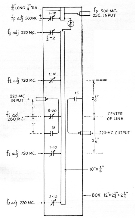
Fig. 3. Dimensions of the 220 Mc parametric amplifier. The 220 Mc tuned circuit is a half-wave line. Pump energy is fed into the short line at the top of the amplifier.
The sketch in Fig. 3 gives the essential dimension and locations of capacitors for the 220 Mc amplifier. Aluminum about 1/16 inch thick is suitable for the box if copper (heavy flashing sheet) is used for the end pieces. These should have bent-over lips on all four sides. The ends can be fastened into the aluminum sides with a couple of sheet-metal screws on each side. The ¼ inch diameter center conductor should be soldered into the sheet copper end pieces for the 144 Mc unit. In the 220 and 432 Mc units only one end needs to be copper since the half-wave line is floating free of ground on a pair of small poly or ceramic insulators.
Fig. 4 gives the dimensions found suitable for 144 Mc with a 6 pF varactor. The dimensions in Fig. 5 for the 432 Mc unit are for the same varactor diode. Miniature plate-type capacitors were used at first for tuning, but caused the circuit Q to drop too much. Later, copper solder lugs were made up to fit over the shafts to clamp against the box side, and then bent around for soldering to the ground lugs on the capacitors. The Q went back up and, since several of the glass piston-type trimmers which had been substituted had been broken due to carelessness, the little plate-type capacitors were put back into the 220 and 144 Mc amplifiers.
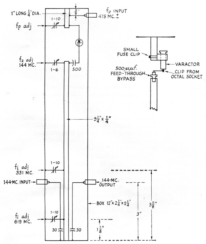
Fig. 4. Dimensions of the 144 Mc amplifier using a quarter-wave line. Method of mounting the varactor is similar to that employed in the 220 Mc amplifier, except for the blocking capacitor needed because of the grounded inner conductor.
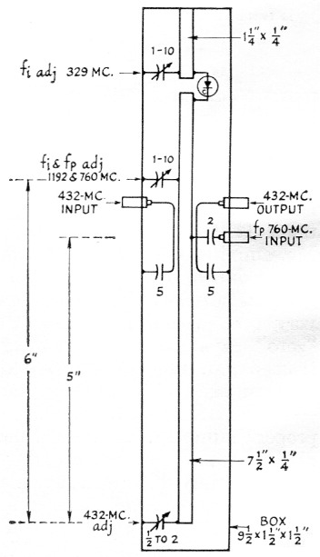
Fig. 5. Dimensions of the 432 Mc amplifier, using half-wave tank circuit. Varactor mounting is similar to that used in the 220 Mc amplifier.
Variable capacitors for the input and output links at 432 Mc. (near the center of the long line) were so large and space-wasting that very small NP0 fixed capacitors were used to tune out most of the link reactance at 432 Mc. Moving the 1-inch long insulated links (BNC coax fitting to 5 pF capacitor) closer to or farther away from the center line is necessary in getting the amplifier to fire up properly. Similarly at 220 Mc, fixed 15 pF ceramic capacitors (with minimum possible lead lengths) were finally used in series with the 2-inch links. At 144 Mc, two 30 pF capacitors were substituted for the 5 to 40 pF capacitors shown in the photograph of this amplifier. The links in this case were 3 inches long (including the capacitor). The 144 Mc unit was modified as shown in Fig. 4 after the photographs were made.
Alignment suggestions and miscellaneous notes
Alignment isn't easy unless one is lucky. Every tuning control reacts on the others, so a lot of patience and a diode noise generator are needed. The first step is to get a reference reading with the receiver connected directly to the noise generator. Then connect the parametric amplifier into the coax line between the noise generator and the receiver. Leave the pump oscillator turned off but have the varactor diode in place. (Handle it carefully!) Tune the end capacitors for best noise figure. If this is more than 20 per cent above the noise figure without the amplifier, adjust the input and output links also. Once you get the noise figure down near the original value, the signal circuit end tuning should be touched up slightly, because it is possible to get amplification off resonance and lose about 1 dB of noise figure. If the unit has a half-wave line, try to get it balanced up so a short circuit with a small screw driver to the box at the line center has no effect on the noise figure.
The next step is to turn on the pump oscillator and slowly increase its output. For safety, keep the oscillator input to less than one-half watt. The pump-circuit tuning and the idler-frequency adjustments have to be worked back and forth until the parametric amplifier begins to show some gain in the output reading with the noise generator on. When the right combination of all tuning: adjustments and correct pump frequency are found, the pump power into the amplifier should be reduced to a point which gives from 5 to 15 db. gain, with the amplifier well below the oscillating point. Connecting to an antenna may upset the amplifier unless the antenna system has a flat line of the same impedance as the noise generator. Again, a slight adjustment of the controls will make the amplifier operate normally with an antenna.
In the three units described here, two 6AF4 parallel-line oscillators are used. One has parallel %-inch rods spaced less than % inch edge to edge, with a small butterfly tuning capacitor at the end opposite the tube. Plate current is fed into the plate side through a 2000 ohm resistor at the center of the line, and a 10,000-ohm grid leak to ground connects to the other rod near its center. The tuning range is from about 700 to 830 Mc. The 425 to 550 Mc oscillator has similar construction with 4 inch lines. These are not ideal, and a more mechanically and electrically stable oscillator for these ranges could be built with a heavy flat-plate line of lower impedance and greater physical length.
The 432 Mc amplifier shown here uses approximately 800 Mc as the pump frequency.(1),(3) By careful adjustment it has been possible to get an improvement of about 3 dB in noise figure over a 416B amplifier normally used at W6AJF on this band.
The 220 Mc amplifier shows nearly 3 dB improvement over a 417A tube amplifier normally used on this band. The 144 Mc unit shows from 1 to 2 dB improvement over a 417A tube amplifier. These improvements indicate that the parametric amplifiers are not far from a noise figure of 1 dB. The 220 Mc unit tuned up most readily with a pump frequency of 520 Mc and the 144 Mc unit with the pump at about 475 Mc. The pump frequencies may be changed a few megacycles without ill effects if the idler adjustments are varied. These frequencies apply only to these particular units with the one varactor used in all three.
Spurious radiation
In some recent tests on the 144 Mc amplifier for spurious output the pump frequency was set at 482 Mc and the adjustments made for best average reception over 144 to 144.2 Mc. The signal generator was connected into one jack at 144.1 Mc. with outputs up to 100,000 microvolts available. The usual 2-meter receiver was disconnected and an APR-1 receiver tuning 300 to 1000 Mc was substituted. By using another signal generator in the 450-Mc. range, the input to the APR-1 receiver could be found by the substitution method. At the pump frequency of 482 Mc the output across 50 ohm measured 80,000 microvolt or 80 millivolt. A high-Q 144 Mc circuit between the antenna and the parametric amplifier is indicated for reducing radiation from this source.
The unwanted output at the two idler frequencies, 626 and 338 Mc, was in direct proportion to the signal input at 144 Mc. It measured 5000 microvolt for a 10,000 microvolt input, 500 for 1000, and 50 for 100, at the lower idler frequency of 338 Mc. At the upper frequency of 626 Mc the outputs were 2000, 200 and 20 microvolt, respectively. Since the parametric amplifier would probably only be used on signals of 1 microvolt or less, the outputs at 338 and 626 would be less than 1 microvolt - not enough radiation to worry about. However, the pump oscillator output would still be up near 80 millivolt, or about 125 microwatts into a 50 ohm dipole. A carefully designed high Q coaxial tank circuit tuned to 144 Mc. would reduce this oscillator radiation by a factor of about 100 without sacrificing more than 1 dB in gain and noise figure. A small neon bulb across the top of this extra tank circuit would probably fire when a high-powered transmitter in the station is keyed, thus protecting the varactor diode against overload when the antenna relay isn't self-shielding for the receiver input side.
Notes
- Bateman and Bain pointed out in March QST that use of a pump frequency of twice the signal frequency fundamentally limits the over-all noise figure to no lower than 3 dB, though noise figure measurements may make it appear that much lower noise figure is being achieved. Ed.
- The author appears to have used a more complex approach than is necessary here. Theory and practice indicate that only the lower of the two idler frequencies need be considered in the design of a parametric amplifier. The relatively low pump frequencies used by W6AJF may account for the need for taking the upper idler frequency into account in his experience. Ed.
- Better results could be obtained with a higher pump frequency. Something of the order of 1500 Mc or higher is recommended for use with 432 Mc amplifiers.
Frank C. Jones, W6AJF.