What value component?
Knowing how to substitute can save you money.
The experienced amateur knows that there is a wide tolerance in the values of many of the components that go into radio circuits, and very often a particular value is specified in a published description simply because it happened to be on hand at the time the circuit was tried out. The beginner, lacking this experience, sometimes misses opportunities to use what he already has, and thus is out of pocket for new parts he didn't really need to buy. This article should help answer the question "Can I substitute a such-and-such for a so-and-so?"
No doubt you have wondered at times how the designer of a piece of radio gear arrives at the values of the different components used in it. Also, you've probably been mystified by the fact that different component values have been used for what seem to be identical purposes in similar pieces of equipment. And - probably more important to you as a prospective builder - you've debated what values can be substituted while still having the unit work as the designer intended.
Actually, there are very few critical values in a piece of radio gear. For example, it is relatively simple to design two transmitters having the same output power and covering the same frequency ranges but with quite different component values in each one. In this article the functions of some of the more commonly used components will be discussed, and the question of what values can be substituted will be considered.
Capacitors
Let's take capacitors first and see what they are used for and what values will be suitable in each application. One of the things a capacitor will do is pass r.f. and audio currents but stop d.c. In radio circuitry it is sometimes necessary to shunt such currents across certain parts of the circuit, and a "bypass" capacitor is used for this purpose. For example, a bypass is usually connected across points in the circuit where the power supply voltages are introduced. The bypass capacitor prevents r.f. from flowing back into the supply. Another case is where a resistor used for d.c. voltage dropping may offer an undesirably high impedance path to r.f. currents; a capacitor is used to bypass the r.f. around the resistance. An example of the uses of bypass capacitors is given in Fig. 1.
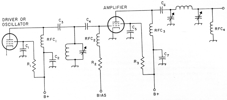
Fig. 1. This typical circuit shows the uses of some of the components in a simple transmitter.
| C1,C2,C5,C7 | Bypass capacitors. |
| C3,C4,C6 | Blocking or coupling capacitors. |
| R1,R3 | Voltage-dropping resistors. |
| R2 | Bias resistor. |
| RFC1,RFC3 | Plate r.f. chokes. |
| RFC2 | Grid r.f. choke. |
| RFC4 | R.f. choke used as safety precaution in the event that Cs breaks down. In such case a dangerous d.c. voltage could appear on the feed line and antenna. With RFC4 in the circuit this voltage is short-circuited if C5 is shorted. |
Capacitors carry a "working voltage" rating that indicates the maximum d.c. voltage that should be allowed to appear across the capacitor. Always use capacitors that have at least as high a rating as that specified by the designer. (It is of course permissible to use units that have a greater voltage rating than specified.) If ratings are not given in the design (and this happens quite frequently) you needn't be at a loss to choose the proper rating; simply determine what the supply voltage is and then use capacitors with ratings equal to or greater than that voltage.
Capacitance values of bypass capacitors are not critical in the 80 through 10 meter range. Values from 1 to 10 nF are commonly used. If you use values much greater than 0.01 µf. you run into two problems. First, the capacitor is likely to have significant inductance and the unit will not be an effective bypass at the frequency for which it was intended. Second, the physical size of the capacitor will be much larger.
In v.h.f. construction, capacitors designed for this type operation should be used. The older style mica and paper capacitors, while they may have the correct capacitance value, are not suited for v.h.f. work. The smallest (physically small) disk capacitors should be used. The biggest value of bypass capacitance is rarely more than 5 nF, and even this value is used only for 6 and 2 meter. U.h.f. work requires special bypasses. The reason for limiting values to 5 nF for v.h.f. work is that greater values will be inductive and physically large. It is important to keep lead lengths as short as possible in v.h.f. work, and this would be impossible if large capacitors were used.
Whenever TVI suppression is a factor special bypassing techniques must be observed. This is a whole story in itself and cannot be covered in this article. However, the BCI-TVI chapter of the Handbook treats the subject in considerable detail.
There is one other factor to consider when deciding on the value of a bypass capacitor. If the r.f. circuit being bypassed carries audio too, as in a modulated amplifier, the capacitance should be limited to a value that will not affect the higher audio frequencies - no more than 2 nF in the ordinary case.
Coupling and blocking capacitors
A "blocking" capacitor is used to couple r.f. r audio) currents from one circuit to another nd to isolate one of the circuits from a d.c. oltage present on the other. An example of the use of blocking capacitors is shown in Fig. 1 at C3, C4 and C6.
"Coupling" and "blocking" capacitors actually perform similar functions, and the two terms are usually interchangeable. The distinction is that the blocking capacitor is a special case of coupling capacitor, in that it has to "block off" d.c. that might be harmful if present on one of the circuits. The blocking function is not always needed, since in some circuit arrangements a coupling capacitor is called for even though no d.c. voltages are involved. However, in most transmitting applications the coupling capacitor is used because d.c. blocking is essential, and it is therefore proper to call it a blocking capacitor.
Capacitance values and voltage ratings are similar to those used for bypasses. In r.f. circuits a minimum value of about 100 pF is customarily used in the 80 through 10 meter range. Any value from 100 pF to 10 nF is permissible in this type of circuit. Occasionally you may encounter circuits where critical values are specified, and in such cases the designer's specifications should be followed.
Power-supply filter capacitors
One of the purposes of a power-supply filter is to smooth out the rectified a.c. voltage and keep the ripple percentage below certain limits. The power-supply ripple should not exceed 5 per cent for c.w. transmitters and should be no more than one per cent for phone rigs. Modulator supplies and those for high-gain speech-amplifiers should be held to considerably lower ripple figures.
The capacitance required in a filter capacitor, for a given ripple percentage, depends on the inductance of the associated filter choke. Let's consider the single section filter shown in Fig. 2A. The percentage of ripple obtained with this type filter is determined by the formula 100 /LC' where L is in henrys and C is in microfarads. It is obvious from the formula that in order to obtain 5 per cent ripple the product of L and C must be at least 20. There is, of course, considerably more to the subject of power-supply filters than can be given here. The Handbook should be consulted for information on other types of circuits.
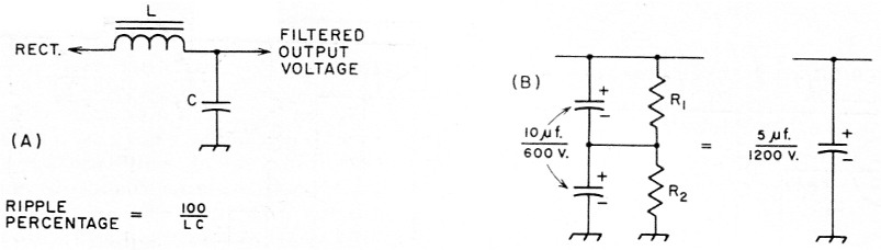
Fig. 2. A typical chocke-input power-supply filter is shown at A. The method of connecting capacitors in series to obtain a higher voltage rating is shown at B. When capacitors are connected in series each capacitor should be shunted with a resistor (R1, R2) with a resistance of about 100 ohm per volt of supply voltage. The resistors can serve as part or all of the bleeder resistor.
The point to keep in mind is that there are certain minimum requirements for component values, and as long as the minimum requirements are satisfied a wide range of values can be used. For example, suppose the designer shows an 8 µF capacitor but you happen to have a 16 µF or 20 µF unit in your junk box. Since your capacitor more than meets the designer's requirements, it can be substituted.
When substituting a different capacitor in a power supply never use one that has a lower voltage rating than specified. You will be safe in assuming that the designer's rating is the minimum.
The use of electrolytic capacitors has until recently been largely confined to low-voltage supplies (up to 600 volt), but there has been a trend in the last few years toward the use of electrolytics in high-voltage supplies as well. By connecting two or more capacitors in series, as in Fig. 2B, the total voltage rating can be increased. For example, two 500 volt, 16 µF electrolytics can be connected in series to obtain a 1000 volt rating, at the expense of halving the capacitance so that the total becomes 8 µF.
Nevertheless, this is often economical; for example, using the two electrolytics to obtain 8 µF at 1000 volt costs approximately $1.75 while a similar capacitance in an oil-filled unit would be about $9. It is permissible to substitute electrolytic capacitors for oil-filled or paper capacitors called for in a design, or in existing equipment. If, for example, a 10 µF 1000 volt unit blows out in a power supply, it could be replaced by two 20 µF 500 volt electrolytics connected in series.
Variable capacitors
A common question asked by beginners is whether they can substitute variable capacitors having different values than those specified in a particular piece of equipment. The answer is yes in many cases. Suppose the circuit calls for a variable that has a minimum capacitance of 15 pF and a maximum of 100 pF and you have a unit that has a range of 10 pF to 150 pF. The range required in the circuit would fall within the limits of your unit so it would be OK to use it. The only time you couldn't substitute would be when your unit doesn't have a low enough minimum capacitance or a large enough maximum. However, designers usually allow a certain amount of "extra" capacitance as a safety factor, and if you know the inductance of the circuit being tuned by the capacitor, you can find out how much range is actually required. One method is to use the ARRL Lightning Calculator. The calculator will show you what capacitance is needed to tune a given range and will also show you how to find the inductance of r.f. coils.
In substituting for a variable capacitor in a transmitter it is just as necessary to keep voltage ratings in mind as in the case of fixed capacitors. Use a variable with at least as much air gap between plates as was used in the original equipment.
Resistors
Resistors are used to provide bias voltages, to reduce or "drop" voltages, as bleeders in power supplies, and in many other applications. Most circuit designs are based on a ± 10 % resistance tolerance because resistors having this value of tolerance are generally available. However, in some cases tolerances are actually specified on a diagram, and in such event substitutions should be within the tolerance of the specified item. (This is, of course, true with any component.) If no tolerance is specified you can substitute any resistor value that falls within the 10 % region.
Resistors can be connected in series or parallel to provide a desired resistance. For example, suppose the circuit calls for a 5000 ohm, 2 watt resistor and you have two 10,000 ohm, 1 watt units on hand. The two resistors can be connected in parallel to provide the 5000 ohm at 2 watt. If you have a well-stocked junk box you'll probably find many combinations that will work in any particular circuit.
Circuit diagrams customarily specify the power ratings of the resistors required in a unit. It is, of course, OK to use resistors with a larger power rating than specified. Watch out for one thing, though: never substitute a resistor that has a power rating less than that called for.
Fixed resistors are supplied in two general types, wire-wound and composition. Never use the ordinary wire-wound type where it would have to carry r.f. Wire-wound resistors have an appreciable amount of inductance, which will upset the operation of an r.f. circuit.
If too much heat is used in soldering or unsoldering composition resistors, particularly the 3 watt size, the resistance value can change. It is a good idea to check previously-used resistors with an ohmmeter before installing them in a piece of gear.
R.F. chokes
Another component that has wide use in radio equipment is the radio-frequency choke. The inductance of an r.f. choke is intentionally made large, with respect to the inductance of a coil used in a tuned circuit, so that it offers a very high impedance at radio frequencies.
Examples of the use of r.f. chokes are shown in Fig. 1. RFC1 and RFC3 are connected in the d.c. leads to the plates of the tubes. These chokes prevent r.f. current from flowing back into the power supply. If a bypass capacitor alone were used for this purpose, the plate tank circuit would be bypassed and the amplifier wouldn't work. By installing the r.f. choke the r.f. currents are prevented from flowing back into the supply but are not prevented from flowing to the tank circuit.
In transmitters in the 80 to 10 meter region choke values from 750 µH to 2.5 mH are commonly used. Tolerances are not "tight" and it is possible to substitute values and have the equipment perform as it is intended to do. In v.h.f. construction, on the other hand, it is a good idea to follow the designer's specifications as closely as possible. In some cases an r.f. choke will work well on most bands but may have a self-resonance in one articular band. When this happens the choke acts as a power-absorbing tuned circuit and will develop "hot spots." If the power level is high enough the choke may actually burn out. A grid-dip meter can be used to check a choke for such resonances. Connect the two ends of choke together with a short length of wire and couple the grid-dip meter to the choke. Tune the grid-dip meter through the bands you plan to use, and if there are any hot spots they'll show up as a dip in the meter reading.
Power transformers
Two factors must be considered when deciding on a transformer substitution - the voltage and current ratings. Let's take current first. You can always substitute a transformer that has a current rating equal to or greater than that called for in the equipment. Transformer manufacturers usually design their transformers for continuous duty, not for amateur service, which can be considered to be intermittent. This means that in many cases transformers used in amateur equipment are underloaded rather than overloaded. Many designers of amateur equipment know this and will take more power from a transformer than its ratings ostensibly would allow.
If you plan to substitute a transformer that has different ratings and are in doubt, there are a couple of ways of working out the problem. If the design tells you the total current requirements you can get a pretty good idea whether your substitution will work. However, this information isn't always furnished, and in such cases you'll have to estimate the total current by adding up the amounts taken by all the tubes.
While it is possible to take more than the rated current, intermittently, from the plate winding of a transformer without seriously overloading it, this is not generally true of the filament or heater windings because the tube filaments usually run continuously. As long as the filament winding rating in your substitute is equal to or greater than the actual heater current demanded by the tubes it is all right to use it. Incidentally, beginners frequently ask if it is OK to use a filament winding that has a greater current rating than is required for the tube or tubes they plan to use. For example, a tube may be rated at 6.3 volts, 1 amp., and the transformer can deliver 5 ampere at 6.3 volt. This doesn't mean that 5 amperes have to flow through the tube heater; the current will be only 1 ampere because that's all the tube will take when the proper voltage - 6.3 volts - is applied to the heater. All that happens is that the transformer winding runs a lot cooler than it would if it were loaded to full capacity.
Where voltage ratings are concerned it is generally possible to substitute transformers that are not exactly the same as originally specified. For example, a transmitter circuit may call for a 400-0-400-volt transformer and you have one giving 350-0-350 on hand. The 350 volt transformer can be used, but the power input will be lower than it would have been with the higher-voltage job. In most cases the difference will not be serious. It may be necessary to increase screen voltages to bring them back up to rating; this is usually a simple matter of reducing the screen-dropping resistance appropriately.
If the output voltage of the substitute transformer is too high, you can use voltage-dropping resistors or a voltage divider to bring the voltage down to what is required. But watch out for the possibility of exceeding filter-capacitor voltage ratings when you do this. The power supply section of the Handbook should be consulted for information of voltage dividers.
Power-Supply Chokes
As shown earlier, the inductance required in a power-supply choke depends on the amount of capacitance used in the filter circuit. Here again, as with other components, there is plenty of flexibility. You are usually safe in substituting chokes that have a larger inductance than the one specified, without making any other changes in the filter circuit, as long as the choke has a similar current rating. As with transformers, the manufacturer's ratings on chokes are for continuous duty, so there is considerable tolerance available for amateur service.
If you have any doubts about substituting certain components in particular applications it is a good idea to use manufacturers' and distributors' catalogs as a reference guide. For example, you may have a wafer switch on hand and aren't sure that it will be suitable for use in an r.f. circuit. The manufacturer's catalog will usually provide this information. The same holds true for voltage and current ratings of components. Additional information on the subject is contained in an excellent article by Geiser1 on capacitors. Also, the Handbook section on components and color codes is a good reference.
Notes
- Geiser, "Choosing capacitors," QST, July, 1958.
Lewis G. McCoy, W1ICP.