Notes on parasitic beams
Some observations based on experiment.
Some of the things discussed in this article - such as voltage unbalance and "squint" with a one-side feed system such as the gamma - haven't had much attention in amateur circles. If some questions about beams have been worrying you, the answers may be here.
During the course of developing a lecture demonstration on parasitic beams, the folowing points were briefly investigated:
- Azimuthal distortion of the radiation pattern with gamma versus balun-matched feed.
- Insulated versus uninsulated elements.
- Effect of varying second and third director element spacings.
- Gamma-rod length versus gamma capacitance with driven-element length in the vicinity of a half wavelength.
The test apparatus
A frequency of 144.008 Mc was chosen in preference to a higher one, to take advantage of readily available standard components. Physical dimensions of antennas at this frequency are such that measurements of length are not too critical, yet the frequency is high enough so that isotropic conditions can be simulated when the antenna is held high aloft in a test rig in an open field. Fig. 1 shows the general layout of the test apparatus.
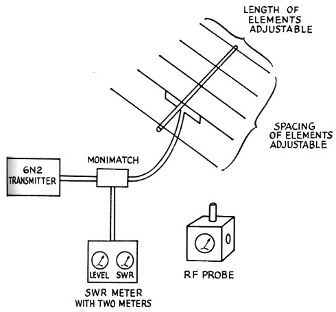
Fig. 1. Equipment used in the test setup.
Validity of measurements
Fig. 2 shows details of the pickup system and radiator. The diode pickup and amplification system was calibrated against a thermogalvanometer pickup dipole and its linearity established. Gain figures obtained for three- and two-element beams over a reference dipole were repeatedly checked and gave consistent results in close agreement with published figures.
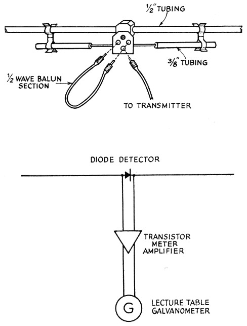
Fig. 2. Detail of radiator feed arrangement and pickup antenna system.
It might be pointed out to those who may want to duplicate these tests that it is much easier to make gain measurements by using a dipole radiator, without parasitic elements, and make the adjustments in length, spacing, number of elements, and so on, to a test array arranged as a pickup system instead of as a radiating system.(1)
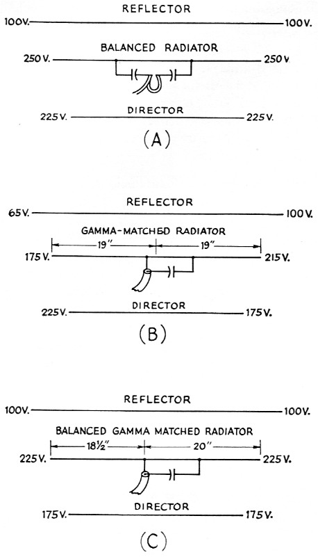
Fig. 3. Relative voltages at ends of elements with (A) Balanced feed-T matching section with balun; (8) Gamma match; (C) Gamma-matched radiator with undriven side shortened to balance voltages at ends of element.
Gamma match versus balun match
Fig. 3 shows relative voltages measured at the ends of a three-element beam with a balun and with a gamma match. The voltages at the opposite ends of an element in a gamma-matched system are indeed unequal, whereas the corresponding voltages with the balun-matched system are equal.
Unequal distribution (unbalance) can be corrected in a gamma-matched system by shortening the side with the lower voltage, as shown in Fig. 3C. Thus one ends up with a lopsided beam, physically, if an attempt is made to balance the voltage distribution.
Lacking an r.f. probe, an approximation of the voltages in a practical beam can be made either by using a neon bulb or by drawing an arc off the ends of the elements. With high power, half-inch arcs can be drawn off the ends of elements, but this is a dangerous practice and not to be recommended. However, if you insist on doing it, tape a pencil to the end of a wooden (not metal) broomstick. For maximum effect, sharpen a soft lead pencil in an automatic pencil sharpener.
The gamma match shows a slightly greater tendency toward radiation from the down lead - that is, the coax feed line - as shown by probing for several wavelengths, but this can be minimized by coiling the feed line in the form of a loose r.f. choke.
However, the most interesting, fact observed was that the azimuthal radia ipn:.patterns were identical with both the gamma and balun match when both halves of the elements were the same length. One would surmise from the above data - and intuition - that azimuthal distortion (squinting) would occur with the gamma. Yet repeated measurements at different heights showed no distortion of the pattern, at least not within the resolution of this system, either inside or outside the Fresnel zone. For these and other tests, a whole football field was available.
The conclusion is that it is not worth the effort to use a balancing system. Experience has shown that the less hardware one has up in the air the less trouble there is with galvanic action. And from a mechanical standpoint the simplicity of unbalanced feed is hard to beat.
Insulated versus uninsulated elements
Element insulation was accomplished in the test setup by substituting a plastic rod for the metal boom. There seemed to be little advantage in insulating elements from the boom. Insulated elements did tend slightly to minimize the voltage unbalance in a gamma-matched system, but in practical systems insulation does not seem worthwhile.
Effect of varying fourth and fifth element spacing
Theoretical gain figures for four- and five-element beams bother many of us, especially when it comes time to cut up a long piece of boom material to conform to precalculated element spacings.
The popular 0.1 and 0.2 wavelength spacings have no magical properties, needless to say, and any intermediate spacings will work. Authors of articles on beam antennas get a large number of inquiries about element spacings, some correspondents wanting to know right to the inch.
The second director (fourth element) was found to be most effective in the vicinity of 0.2 wavelength spacing. Placing this element too close (0.1 wavelength) to the first director produced little gain and sometimes even caused a reduction in gain depending on the tuning. Assuming that this also holds for additional directors, the conclusion is that unless one has an extra long boom which will permit at least 0.2 wavelength spacing between directors, one is liable to suffer deterioration in gain by adding extra elements.
The 20 meter four element beam at KH6IJ uses a 42-foot boom with 0.2-wavelength spacing between elements. After five years of evaluation against a close-spaced four-element reference beam, the conclusion is that the gain and bandwidth are as predicted, and that the front to back ratio is not as pronounced as with the close-spaced beam. But the mechanical difficulties of putting up and maintaining a long-boom beam are formidable. This beam was smashed to smithereens by a 105-m.p.h. hurricane which snapped the 16-inch butt of an 80-foot telephone pole supporting it. The pole fell on the beam, which had been lowered before the storm.
Gamma rod length versus gamma capacitance in the vicinity of a half wave
Practical adjustment of a gamma-matched beam has been covered in a previous article,(2) step procedures for which were derived in part from this experiment.
The following relationships hold:
- The longer the radiator (departure from true half wave) the shorter the gamma rod length required, and vice versa.
- The longer the gamma rod the less gamma capacitance required, and vice versa.
Axiomatically, an infinite number of combinations of gamma capacitance, rod length, and radiator length is possible. However, experimental measurements show that only one combination will result in the lowest s.w.r. consistent with good bandwidth and gain.
The following conclusions were drawn from some experiments:
- It is possible to resonate and match, with reasonable s.w.r., almost any length of radiator. In one interesting accident, the end section of the radiator of a 20-meter beam was inadvertently left off, but by judicious use of gamma rod length and capacitance the system was made to show a reasonable s.w.r.
- Maximum bandwidth is attainable with a radiator length as close to an electrical half wave as possible. However, as pointed out in a previous article,(2) better and easier matching is possible with the radiator cut slightly shorter than the standard 470 divided by frequency in megacycles.
Fig. 4A shows the electrical equivalent of a gamma-matched three-element beam. The gamma-rod section represents a section of feed line less than a quarter wave long terminated in a load less than its characteristic impedance, and therefore always presents an inductive reactance which must be cancelled out by the series gamma. capacitor.
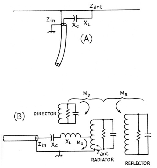
Fig. 4. (A) Gamma-match with impedances indicated;
(B) Approximate lumped-circuit equivalent for a three-element antenna.
Fig. 5 shows data obtained in a series of experiments in which gamma rod lengths were balanced off by gamma, capacitance to obtain minimum s.w.r. The plot shows the nature of the curve of gamma capacitance required. Most amateur beams using 72-ohm coax end up using a gamma rod length which is in the region where a small change in length makes a comparatively large change in the impedance seen by the feed line, which explains why the rod lengths and capacitance values are so critical.
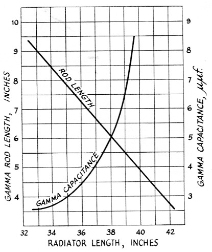
Fig. 5. Gamma rod length and series capacitance required for matching to coax line as a function of antenna length, at a frequency of slightly over 144 Mc.
Again referring to Fig. 4B, we might consider the matching section (gamma rod and capacitor) as similar to a conventional tuned circuit, the resonant frequency of which is determined by the loop Xc, Xr, and ZANT. The inductive reactance X1, is to be cancelled by Xc. The difficulty with this oversimplification lies in the mutual coupling (Mn, MR) which exists between radiator and reflector and director, complicated further by the fact that part of the matching section (MG) is also a radiator.
A change in any one of these parameters is immediately reflected as a change in resonant frequency, with a consequent change in s.w.r. Under these circumstances there is no recourse but cut and try, a practical step procedure for which has been covered in a previous article.(2)
Of interest is Fig. 6, which shows a typical plot of change of s.w.r. with rotation of the antenna. This was made at 144 Mc, but at lower frequencies the "people," "metal table," and "floor lamp" might just as well be a tree, power line, or portion of the house. Which way was your beam pointed when the s.w.r. run was made?
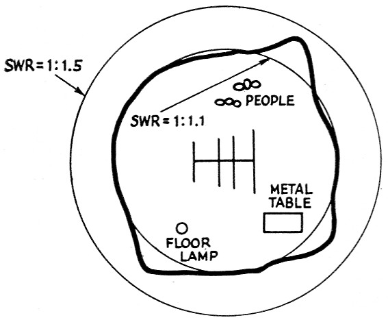
Fig. 6. Variation of s.w.r. on feed line as antenna was rotated, with various objects in near field.
As W2AWH(3) points out, perhaps we are making a fetish of s.w.r., and in most instances it is just a conversation piece. But it's mighty comforting to know that yours is "right on the nose" (no pun intended!).
Notes
- The method should be used with some caution, however, since each adjustment has an effect on the antenna feed-point impedance and thus on the match bets een the antenna and line. This in turn affects the efficiency of power transfer to the receiver or other indicating device. For accurate results, rematching is required after each adjustment that changes the antenna impedance significantly. - Editor.
- Nose, "Adjustment of gamma-matched parasitic beams," QST, March, 1958.
- Beers, "Match, or not to match?," QST, September, 1958.
Katashi Nose, KH6IJ.