Polarized relay in the rtty converter
I enjoyed the article by WOLQV in the December issue on teletype conversion, although I have not had an opportunity to build the equipment. The comments which follow are on the use of the keying relay, K1 (refer to my article, "Some Hints on Relay Operation," June 1956 QST).
The use of a Sigma 7JOZ-160T (160 ohms per coil) is justified only if the ham already owns one or can get one at a bargain price. This relay has not been manufactured for about five years, but it is practically identical with Type 7JOZT-150T still being made. If either of these two is used, it is not necessary to run it "biased"; i.e., with keyed current in one coil and fixed current in the other. 1f the parallel 6AQ5s are eliminated and a 6SN7 or equivalent substituted for the second trigger tube (12AU7 in Fig. 1) the relay should operate properly with one coil connected in each plate circuit. The grid bias should be adjusted so that each half draws about 15 ma. when conducting.
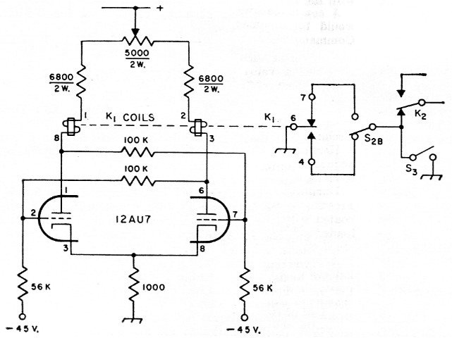
Fig. 1. Suggested alternative circuit using a dual-coil plate-circuit type relay, for the radioteletype converter described by J. L McCoy, W0LQV, in January 1960 QST. The relay should have 1000 ohm coils. Suitable Sigma types are the 7JOZT-l000T, 7AOZT-1000T, 7ROZT-1000T, and 72A01-1000TG.
However, for vacuum-tube circuits running with 200 volt or more of "B" supply, a higher coil resistance is more suitable since it operates on less current. The "ideal" relay for the job would be one with dual 1000 ohm coils. In decreasing order of cost these would be the 7JOZT1000T, 7AOZT-1000T, and 7ROZT-1000T. They differ only as to their enclosures, the first being hermetically sealed, a feature not needed by hams.
We breadboarded the second trigger stage, using the 12AU7 only, placing each relay coil in series with the load resistor (these were changed to 10,000 ohm). The 6AQ5 stage was omitted entirely. Operation was entirely satisfactory. The reversal accomplished by switches Sea and 820 could be handled either by reversing the coils or by reversing the fixed contacts of the relay. I suggest the circuit modification shown in the accompanying sketch. The 5000 ohm potentiometer enables one to correct for any unbalance in the tube currents. Perhaps increasing the 100 k feedback resistors would permit returning the grids to ground instead of to -45 volts, but this we have not tested. Sea now reverses the contacts of Ki and Sac is not required.
Hams wanting more dope can get it from me at the above QTH.
L. B. Stein, jr., W1BIY.