An improved audio-driven a.g.c. circuit
Residual voltage to ground or leakage is often a source of trouble in high-resistance a.g.c. circuits with no-signal or small-signal input. The lower-resistance circuit described here includes means for setting the line at ground potential.
Lower resistance circuit with better performance at low signal levels.
Automatic gain control circuits requiring an extremely high d.c. resistance between the a.g.c. line and ground are sometimes subject to troubles arising from slight grid emission or gasiness of controlled tubes, or from contact potentials developed in diodes connected to the a.g.c. line. A consequence of any of these is that the a.g.c. line may not be at ground potential in the absence of signal or with a weak signal, and tube aging may cause drift. If the a.g.c. line is not at ground potential with no signal, the actual grid bias on the controlled tubes will differ from the design value by the voltage between the a.g.c. line and ground, and this difference may not be negligible.
To give a specific illustration, the "audiohang" a.g.c. circuit described by Luick(1) and shown in the 1960 ARRL Handbook was applied to a receiver using three gain-controlled 6BZ6 tubes. It was found that the a.g.c. line was standing at nearly one volt positive to ground, due mainly to contact potential developed in the discharge triode V1B in Luick's circuit. As a consequence, the actual grid-to-cathode bias was only about 1.5 volt instead of the 2.5 volt desired.
In another instance, a slightly gassy tube was found to be discharging the a.g.c. line very rapidly, after it had been driven negative by rectified audio signals, and the timing circuit connected to the grid of the discharge triode V1B had little or no effect on the actual a.g.c. time constant. In a third instance, a tube having some internal leakage between grid and cathode (4 megohm) was also found to cause rapid discharge, thus rendering the intended timing circuit quite ineffective. These slightly imperfect tubes were new, and worked well enough in other places.
These troubles stem from the necessarily extremely high d.c. resistance between the a.g.c. line and ground in this circuit, whereby a very slight unintended current flow to or from the line may change its resting voltage, or its own time constant, quite seriously. An a.g.c. circuit having much lower d.c. resistance to ground minimizes such troubles.
An audio-driven a.g.c. circuit having a very much lower d.c. resistance between a.g.c. line and ground (about 0.1 megohm or less) is shown in Fig. 1. The small plate current (about 2 ma.) of triode VIA flows through cathode resistor R3 (4700 ohms) and produces a voltage drop across it of about 8 volts. The a.g.c. line is tied through RI to the cathode, and the lower end of R3 goes to a source of negative voltage equal to the normal drop across R3. It is this latter feature which permits setting the resting or no-signal potential of the a.g.c. line equal to ground potential. When the voltage drop through R3 equals the voltage of the source connected to its lower end, the two voltages cancel, and the cathode stands at ground potential.
V1B amplifies the incoming audio signal. When the amplified signal exceeds the delay bias established at the junction of R5 and R6 (about 10 volts with the resistor values shown), diode V2 conducts and charges C1 rapidly. The negatively-charged end of C1 is directly connected to the grid of V1A. Thus the cathode current of V1A decreases, and the cathode voltage instantly goes negative to ground, carrying the a.g.c. line with it. If the audio signal is strong enough to result in cutting off V1A completely, the a.g.c. line will drop to -8 volts. Different ranges of control may readily be had by change of the negative voltage to which R3 is connected, and by compensating changes in R3 or R2, or both, to achieve equality of the voltage drop in R3 with the negative voltage chosen. The value of -8 volts was found amply adequate for the three tubes mentioned.
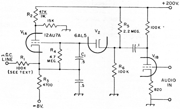
Fig. 1. Circuit of the improved audio-driven a.g.c. circuit. Resistances are in ohms and capacitances are in µF Resistors are ½ watt. Component labels refer to text.
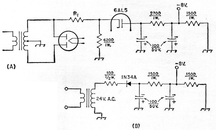
Fig. 2. Suggested circuits for obtaining the required biasing voltage. In A, a rectifier is fed from a voltage divider across half of the receiver's high-voltage transformer secondary. In B, a separate 24 volt transformer is used.
Resistances are in ohms and capacitances are in µF. The value of R1 should be adjusted to give the required output voltage (approximately 50,000 to 150,000 ohm, 5 watt, depending on transformer voltage). Capacitors are electrolytic.
Once C1 is charged by rectified audio signal, it can discharge only through resistor R4. The combination of C1 and R4 shown will provide a discharge time constant of about 2.5 seconds, but greater or lesser time constants may be had by using larger or smaller values for R4. For c.w. and s.s.b., R4 might well be 10 megohms, although where fast recovery is needed the resistance should perhaps be something less than 4.7 megohms. It is sometimes desirable to provide a range of time constants, by switching R4.
The value of resistor R1 is not critical, but can conveniently be 100K ohms or less. If the total capacitance from the a.g.c. line to ground is, say, 0.03 µf., the use of 100K for R1 will introduce only an imperceptible lengthening of the attack time.
Bias source
The supply for the -8 volts need not be par ticularly "stiff" but the output should be well filtered. If the receiver is already provided with a negative voltage source, this can be tapped at -8 volts or whatever is desired. Otherwise, the negative voltage can be obtained in any of several ways. It may be obtained by use of a diode rectifier and filter connected, through a suitably high resistance, between one side of the high-voltage a.c. winding of the power-supply transformer and ground, as shown in Fig. 2A. In my case, the power transformer had an unused 24-volt secondary, and the -8 volt was readily obtained from this by use of a 1N34 diode, three resistors, and two low-voltage 100 µF electrolytic capacitors as shown at B. Perhaps a 12.6 volt a.c. winding, already used for heaters, could be used in this manner. Diode V2 can be half of a 6AL5, and the other half could be used as a rectifier to provide, along with a filter, the needed negative voltage.
The only trick in adjusting the circuit initially is to choose a value for R2 so that the voltage drop across R3 is equal to the negative voltage to which the lower end of R3 is connected. The resting cathode current of V1A should be kept low, a value of, say, 2 mA being desirable.
In practice the circuit works very well, and is free from most of the troubles likely to plague a.g.c. circuits requiring very high d.c. resistance to ground.
Notes
- Luick, "Improved a.v.c. for side band and c.w.," QST. October. 1957.
Hubert Woods, W9IK.