A dummy load off the mind
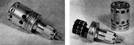
The dummy antenna is enclosed in a 35 mm film can mounted on a coax connector. The nine 1 watt resistors are soldered to copper disks with practically all of the wire leads eliminated.
Practilly the same day that March QST arrived, the writer had been searching handbooks for verification of procedure for making a dummy load. The cover and accompanying article were a resl surprise.
To absorb the transmitter's 7 watt output, EPT's configuration of nine 470 ohm resistors 1 was selected. The soft, foil-like flashing copper happened to be little more than arm's reach away and proved an ideal support. (For those who will follow suit and build similar loads: Be sure to burnish both sides of the copper disks and tin fully before assembling and soldering.)
To add a personal touch, there had to be some "modification." A trim little screw-top aluminum can that is used to package a 35 mm film cartridge was adopted as a housing for the dummy. A pattern of ¼ inch diameter holes was drilled through the side and end. A hole was made in the screw cap to receive a coax reducer bushing, which threads into the coax fitting, making a very rigid mechanical joint. The housing serves as a flue to increase the flow of air when the dummy load is operated in its vertical position, as well as giving protection to the assembly of resistors inside.
The s.w.r. was practically 1:1 - almost as good as the antenna itself. After running the dummy for five consecutive periods of two minutes each while checking s.w.r. at different frequencies, it didn't go up in smoke. Resistance still checked out O.K. on a meter.
Thanks, EPT, for getting us away from the habit of snatching those light bulbs!
Notes
- Tilton, "V.H.F Dummy Loads," QST, March, 1960.
John Howard, K8MME.