High-frequency crystal filters for s.s.b.
Design procedure plus a high-performance unit using surplus crystals.
Here's a two-in-one special - enough information on h.f. crystal filters to design one for most any frequency, band width and shape factor, and also a ready-tobuild 5.5 Mc filter for s.s.b. transceiving.
Many articles have appeared in QST describing crystal filters for s.s.b. operation.(1-5) However, none of these supplied a design procedure and also gave the precise performance of the resulting filters. This article describes a particular type of filter that was built for a homemade transceiver.
The theoretical shape of the selectivity characteristic attainable with simple crystal filter arrangements was calculated first and found to be inadequate for good sideband suppression. The effect of mismatch when filter sections are cascaded without vacuum-tube isolation improved the steepness of the selectivity characteristic, but at the expense of ripple in the pass band. By inserting a small resistance between two sections of a three-section filter, the ripple was reduced without greatly affecting the shape factor (ratio of the bandwidth at some high attenuation to the bandwidth at low attenuation) of the selectivity curve. A filter constructed according to this design from FT-243 surplus crystals performed as predicted.
In filters such as the one used in the transceiver described by W3TLN(6) it is not unusual to obtain spurious responses as close as 15 kc to the pass band which are suppressed by only about 20 dB. In the filter described in this article the spurious responses are attenuated more than 50 dB even with a crystal whose principal spurious frequency was only 7 dB down from the main response.
Simple filter sections
Fig. 1 shows the equivalent circuit of a crystal neglecting its spurious modes. This circuit has the reactance vs. frequency curve shown in Fig. 2. L and C are series resonant at fr, and fa is the antiresonant frequency of C, and the LC combination. By utilizing crystals in a lattice structure as shown in Fig. 3, a selective filter is obtained. The lattice is a bridge, and it is obvious that maximum unbalance of the bridge will occur when one arm has an impedance which is capacitive while the other arm is inductive. When the impedances are equal, the bridge will be balanced. The reactance frequency curves of the crystals can then be used to indicate the regions of the pass band and the stop band. Fig. 4 shows what happens when the anti-resonant frequency of one pair of crystals is made equal to the resonant frequency of the other pair. It is observed that the pass band of a simple lattice is limited to the region between the antiresonant frequency of the higher-frequency crystals and the resonant frequency of the lower-frequency crystals. For the case where the reactance curves in the stop band are equal only at zero frequency and infinite frequency, analysis of the circuit shows that the frequency difference f2 - f1 corresponds to the bandwidth at which the attenuation is approximately 7 dB.
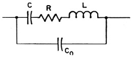
Fig. 1. Equivalent circuit of a crystal. C and L are the motional capacitance and inductance of the crystal, and R represents the frictional loss. Co is the electrode and holder capacitance shunting the crystal.
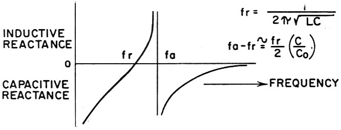
Fig. 2. Reactance vs. frequency characteristics of a crystal. The series-resonant frequency, fr, is that of C and L. The anti-(parallel) resonant frequency, fa, is that of the circuit formed by C and L in one branch and Co in the other.
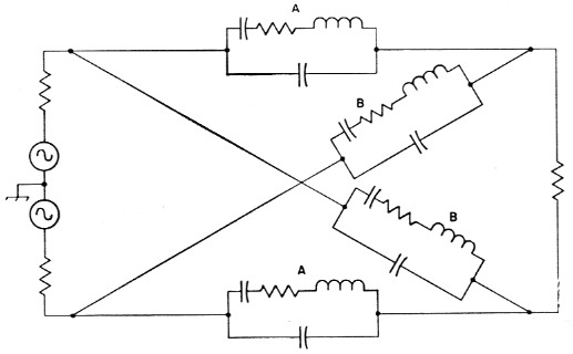
Fig. 3. Equivalent circuit of a full lattice crystal filter. The series crystals, A, are the same frequency, as are the shunt crystals, B. Note that the lattice could be redrawn as a bridge circuit.
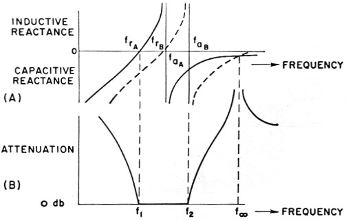
Fig. 4. (A) Reactance characteristics of crystals A and B in the lattice of Fig. 3. In the type of filter described in this article, the series-resonant frequency of the higher-frequency crystal, frB is made equal to the antiresonant frequency of the lower-frequency crystal, faA.
(B) Attenuation curve of a filter using the crystals of (A). In the pass band between f1 and f2 the series and shunt reactances are opposite, the bridge is unbalanced, and nearly all of the input signal appears at the output. At other frequencies the reactances are similar, and the bridge approaches balance and shows little output.
The resistive component of the crystal may be transformed to an equivalent parallel resistance shunting the crystal which is essentially constant for the small frequency range of concern. If all crystals have the same Q and inductance, then the equivalent resistance shunting the crystals ie the same, and if one considers the resistive bridge thus formed, it is balanced under these conditions. The loss resistance can then be neglected except as it modifies the termination of the filter and affects insertion loss. The point is that the filter behaves essentially as though its elements had infinite Q.
Identical results can be obtained with half as many crystals in a half-lattice circuit. As shown in Fig. 5, this is the equivalent of a full lattice in which the impedances of the elements are one half those of the half lattice. The basic circuit, Fig. 5B, shows two crystals and an ideal transformer having unity coupling. A practical transformer which does not have unity coupling can be represented by the circuit of Fig. 5C. Leakage reactance appears in series with the crystals of the lattice and will lower their resonant frequencies. In narrow-band filters, this can be prevented by connecting a capacitor which resonates with the leakage inductance at the center frequency of the filter in series with the center tap(7) as in Fig. 5D. This allows a simple center-tapped coil to be used for the ideal transformer.
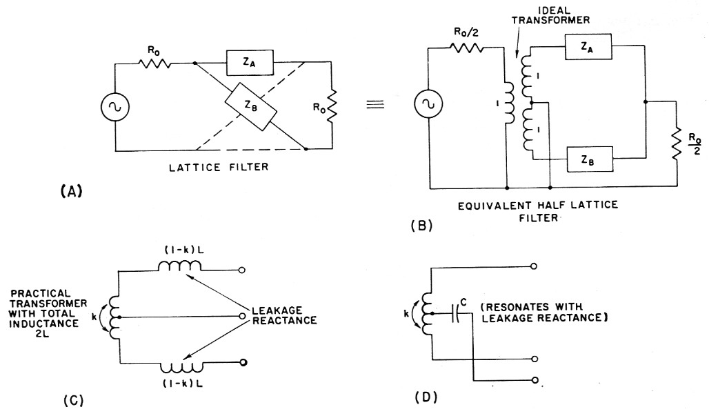
Fig. 5.
Designing an s.s.b. Filter
In building a filter for a transceiver, an intermediate frequency of 5500 kc was selected. This choice is satisfactory for 100 dB suppression of spurious signals in the receiver except on 15 meters. There a 5th-order intermodulation product falls in the pass band so that with a simple mixer the spurious response is only attenuated 75 dB. However, by using a simple balanced mixer, the desired suppression of 100 dB is realized. The balanced mixer also reduces the preselection requirements on other bands.
Since the pass band is on the order of twice fa - fr, this frequency difference must be about 1500 c.p.s. for a filter capable of passing the voice frequencies. The second formula in Fig. 2 shows that fa - fr depends on the ratio of the capacitance shunting the crystal to the motional capacitance of the crystal. For AT-cut crystals (the ones you get for $2.95), this ratio is about 250 minimum. Therefore, AT-cut crystals above 750 kc. meet the requirements, and capacitive terminations are feasible. For example, the shunt capacitance, Co, of a typical AT-cut crystal is about 3 pF. If it is desired to terminate a half-lattice filter with a circuit capacitance of, say, 15 pF, this will reflect as a total shunt C of 15/2 + 3 = 10.5 pF across each crystal. Under such conditions, AT-cut crystals can be used for amateur s.s.b. applications at any frequency above 2625 kc.
Surplus FT-243 crystals (BT-cut) are available for 5500 kc, and their use is economically attractive. BT-cut crystals, however, have Co/C ratios around 4000 minimum, which is too high to allow the desired pass band to be obtained. The pass band can be widened by paralleling inductance with the crystals. This will raise their antiresonant frequencies and leave their resonant frequencies unchanged. One must be cautious in doing this since the inductance will also be antiresonant with the total effective capacitance of the crystal at some lower frequency, f∞, in Fig. 6. If this new frequency of infinite attenuation is too close to the center frequency of the filter, the pass-band characteristics may be distorted.
Measurements made on an FT-243 crystal resonant at 5502.195 kc showed a motional capacitance, C, of 0.0038 µ uf. and a shunt capacitance, Co, of 14.7 pF. The spacing between the resonant and antiresonant frequencies is therefore ![]() or 711 c.p.s. To provide a desired spacing of, say, 1422 c.p.s., the effective shunt capacitance must be reduced to one half the value of Co. This would require the addition of a negative capacitance of 14.7/2 = 7.35 pF. If an inductance, Lo, in parallel with capacitance, Co, is considered, the susceptance of the parallel combination is given by
or 711 c.p.s. To provide a desired spacing of, say, 1422 c.p.s., the effective shunt capacitance must be reduced to one half the value of Co. This would require the addition of a negative capacitance of 14.7/2 = 7.35 pF. If an inductance, Lo, in parallel with capacitance, Co, is considered, the susceptance of the parallel combination is given by
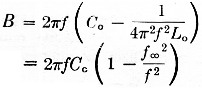
where f∞ is the antiresonant frequency of Lo and Co. (The capacitive contribution of the motional capacitance and inductance below their resonant frequency is small enough to be neglected.) For the case above, it is desired to reduce the susceptance of Co alone, 2πfCo, by a factor of one half. This means that ![]() must equal ½, so Lo, and Co must be antiresonant at 0.707 times the filter frequency, or about 3889 kc for the 5500 kc filter. Higher values of f∞ will also work as long as they are not too close to the center frequency.
must equal ½, so Lo, and Co must be antiresonant at 0.707 times the filter frequency, or about 3889 kc for the 5500 kc filter. Higher values of f∞ will also work as long as they are not too close to the center frequency.
For convenience, the filter was built with input and output coils which resonate with 56 pF plus about 10 pF tube and circuit capacitance. This is equivalent to about 33 pF across each crystal, or a total effective Co of 47.7 pF. Since the effective Co, desired is only 7.35 pF, ![]() and f∞ is 0.92 times the filter frequency, or 5060 kc. This new frequency of infinite attenuation, due to resonance between the coil paralleling the crystal and the total capacitance, is sufficiently removed from the center frequency so that it has negligible effect on the pass-band shape. Design equations for narrow-band capacitor-only filter circuits should therefore be sufficiently accurate for a filter built around FT-243 crystals at 5500 kc.
and f∞ is 0.92 times the filter frequency, or 5060 kc. This new frequency of infinite attenuation, due to resonance between the coil paralleling the crystal and the total capacitance, is sufficiently removed from the center frequency so that it has negligible effect on the pass-band shape. Design equations for narrow-band capacitor-only filter circuits should therefore be sufficiently accurate for a filter built around FT-243 crystals at 5500 kc.
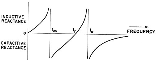
Fig. 6 - Reactance vs. frequency characteristics of a crystal and inductance, Lo, in parallel, fr, the resonant frequency of C and L, the motional capacitance and inductance of the crystal, is the same as in Fig. 2. fa, however, is higher than the antiresonant frequency of the crystal alone, since La decreases the effective inductance across shunt capacitance Cc at frequencies above fr. Lo is also antiresonant with the total effective capacitance of the crystal at some lower frequency, f∞.
For narrow-band filters of this type it is convenient to describe the selectivity characteristic in terms of a normalized frequency variable, Z
![]()
where f1 is the resonant frequency of the lower-frequency crystal, f2 is the antiresonant frequency of the higher-frequency crystal as modified by the circuit, and fo = ½(f1 + f2), the center frequency of the filter.
Fig. 7 shows the selectivity characteristics of two- and three-section filters (each section being two crystals in a half lattice) when the effects of mismatch between sections(8) are neglected. Note that these are normalized curves, plotted in terms of the variable Z. The equations from which these and the other response curves were obtained are given in the Appendix.
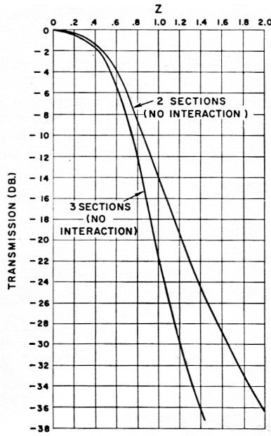
Fig. 7. Theoretical selectivity characteristics of two and three cascaded identical Otter sections when interaction due to mismatch between the sections is ignored. Z is the normalized frequency variable defined in the text. It is proportional to the frequency difference from the center of the pass band.
If we consider only two sections and a 6 dB bandwidth of 2400 c.p.s., the upper curve of Fig. 7 tells us that Z = 0.7 corresponds to 1200 c.p.s. In these plots, Z is proportional to the separation from the center of the pass band. If we assume a low audio cutoff of 300 c.p.s., the carrier must be 1200 + 300 = 1500 c.p.s. from the center frequency. Therefore, the carrier must lie at
![]()
At this frequency the carrier attenuation would only be about 10.5 dB. The undesired sideband would extend from ![]() to
to ![]() The corresponding sideband suppression would vary between 15.4 and 43.2 dB.
The corresponding sideband suppression would vary between 15.4 and 43.2 dB.
This is not adequate for our purpose so three sections must be considered. Here, the 6-db. down frequencies correspond to Z = 0.617. Carrier rejection would be 11.6 db. and sideband suppression varies between 17.9 and 58.4 dB. This still does not meet our requirement, which is 30 to 40 dB suppression of, the undesired sideband with a low audio cutoff of 300 c.p.s., and about 20 dB carrier rejection due to filter selectivity.
Fortunately, the interaction which occurs due to mismatch between cascaded identical filter sections will help us achieve this goal. Fig. 8 shows the selectivity characteristics of two- and three-section filters when effects of mismatch are taken into account. As can be seen, these curves are much steeper than those of Fig. 7.
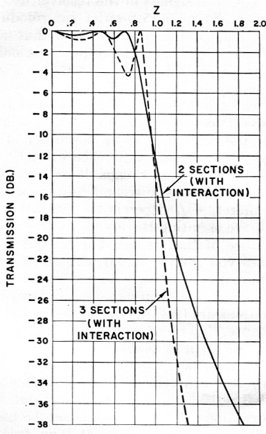
Fig. 8. Theoretical selectivity characteristics of two and three cascaded identical filter sections when interaction is taken into account. These curves are steeper than those of Fig. 7, but there is considerable ripple in the pass band.
Consider as before a 6 dB bandwidth of 2400 c.p.s. For three sections, 1200 c.p.s. corresponds to Z = 0.91, and at the carrier frequency ![]() At this value of Z, the rejection is 26.5 dB. At the low audio end of the undesired sideband,
At this value of Z, the rejection is 26.5 dB. At the low audio end of the undesired sideband, ![]() and the attenuation is 40.5 dB. Thus the three identical crystal filter sections satisfy our requirements.
and the attenuation is 40.5 dB. Thus the three identical crystal filter sections satisfy our requirements.
If we build three sections and reduce the interaction of one section, the attenuation characteristic becomes that shown in Fig. 9. The large pass-band ripple of Fig. 8 is reduced, and by allowing some interaction but not the full interaction of one section, tile pass band can be made nearly flat. In Fig. 9, Z = 0.8 when the response is 6 dB down. If we again consider a 2400 c.p.s. bandwidth and 300 c.p.s. audio cutoff, Z = 0.8 × 1500/1200 = 1.0 at the carrier frequency; the corresponding attenuation from Fig. 9 is 19 dB. The undesired sideband extends from Z = 1.2 to Z = 2.8, so sideband attenuation will range from 30.3 to greater than 60 dB. Such a filter will meet the requirements as well as provide a flat pass band. The shape factor for 30 dB/6 dB is 1.49 and for 60 dB/6 dB, about 2.5.
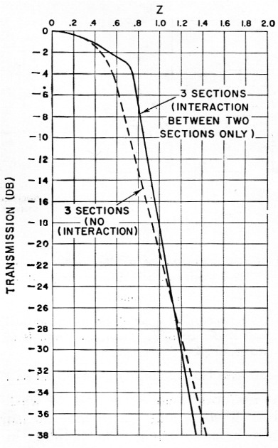
Fig. 9. The solid curve shows the selectivity of a three-section filter with interaction between two sections only. This design is an excellent compromise between those of Figs. 7 and 8. The dashed curve drawn for comparison is for a three-section filter without interaction.
Since Z = 0.8 1200 c.p.s. from the center frequency, these values can be substituted into the equation which defined Z. Solving for f2 - f1 gives a value of 2 × 1200/0.8, or 3000 c.p.s. The resonant and effective antiresonant frequencies of each crystal should therefore be separated by half this amount or 1500 c.p.s. The resonant frequencies of the two sets of crystals should also differ by 1500 c.p.s. Table 1 lists the measured characteristics(9) of the crystals actually used. Crystals 1-3 are resonant near 5502.2 kc; crystals 4-6 are near 5503.9 kc, giving a separation of 1700 c.p.s.
| No. | fr (cps) | C (pF) | Co (pF) | frs1 (cps) | Att. frs1 (dB) | frs2 (cps) | Att. frs2 (dB) |
|---|---|---|---|---|---|---|---|
| 1 | 5502195 | 0.00380 | 14.7 | 5516800 | 9 | 5559800 | 12 |
| 2 | 5502227 | 0.00356 | 12.3 | 5519900 | 13.5 | 5552000 | 15.5 |
| 3 | 5502212 | 0.00290 | 12.7 | 1 | > 152 | 1 | > 152 |
| 4 | 5503960 | 0.00334 | 12.3 | 5523000 | 9 | 5547200 | 9 |
| 5 | 5503927 | 0.00348 | 14.0 | 5536200 | 7 | 5570200 | 7.5 |
| 6 | 5503860 | 0.00311 | 13.8 | 1 | > 202 | 1 | > 202 |
| 1 | These frequencies were not recorded. | ||||||
| 2 | Attenuation greater than figures shown. | ||||||
The impedance of a filter such as this is given by the expression(10) ![]() . Co' is the shunt capacitance of the crystal plus the reflected circuit and tuning capacitance or about 47.7 pF as shown earlier. f1 is the resonant frequency of the lower-frequency crystals, 5502.2 kc f2 is the antiresonant frequency of the higher-frequency crystals, which is 5503.9, kc plus about 1500 c.p.s. or 5505.4 kc f∞ is 5060 kc as calculated above. Putting these values, into the equation gives a value of 3920 ohm for Ro. In a half lattice the termination should be Ro/2 or 1960 ohm.
. Co' is the shunt capacitance of the crystal plus the reflected circuit and tuning capacitance or about 47.7 pF as shown earlier. f1 is the resonant frequency of the lower-frequency crystals, 5502.2 kc f2 is the antiresonant frequency of the higher-frequency crystals, which is 5503.9, kc plus about 1500 c.p.s. or 5505.4 kc f∞ is 5060 kc as calculated above. Putting these values, into the equation gives a value of 3920 ohm for Ro. In a half lattice the termination should be Ro/2 or 1960 ohm.
2000 ohm terminations are used with the filter than was built. Slight variations in the terminations from these values will affect the selectivity only a small amount and can be used to get aliiibst flat pass-band response.
The effective parallel resistance of the coils is about ten times the filter impedance and has negligible effect on the filter characteristics.(11)
Fig. 10 is a diagram of the complete filter. The first two sections are connected "back to back," and full interaction takes place. The 300 ohm resistor between sections two and three reduces interaction and smooths the pass-band response as shown above. The leakage reactance between the two halves of L2 and L3 is tuned out by the capacitors connected in series with the center taps of these coils. L1 and L4, the input and output coils, resonate with the calculated value of terminating capacitance at 5060 kc and effectively reflect the needed inductance across the crystals. The 2000 ohm resistors complete the termination called for by the design equations.
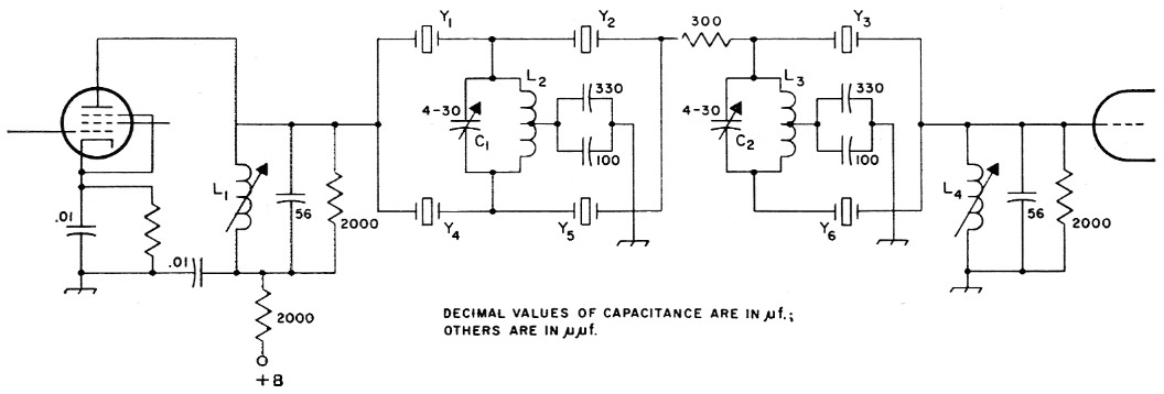
Fig. 10. Circuit diagram of a filter designed according to the methods of this article. Resistances are in ohms, and resistors are ½ watt composition; capacitors are disk ceramic except as noted.
| C1,C2 | 4-30 pF mica trimmer. |
| L1,L4 | 50 turns No. 38 enamel, close-wound on 17/64 inch diem. ceramic slug-tuned form (CTC LS-6, National XR-81 or similar). |
| L2,L3 | 60 turns No. 38 enamel, close-wound on 17/64 inch ceramic form (CTC LS-6, National XR-81 or similar with powdered-iron core removed), center tapped. |
| Y1,Y2,Y3 | All same frequency (near 5500 kc). |
| Y4,Y5,Y6 | All same frequency and 1500 to 1700 c.p.s. different from Y1, Y2 and Y3. |
All the crystals were purchased as 5500 kc FT-243s and etched to the desired frequencies with hydrofluoric acid. It is best to wash each crystal with soap and water and measure its frequency before etching. The crystals in each set of three should be as close to each other in frequency as possible, and the separation between the two groups should be about 1500 c.p.s. A simple comparator circuit(12) will allow two crystals to be checked simultaneously and compared, using an oscilloscope and audio oscillator to measure the frequency separation.
Tuning the filter is quite simple since all four adjustments can be peaked for maximum output at a fixed alignment frequency. This frequency should be on the high side of the pass band and can be the carrier frequency used for lower side-band transmission (5505.5 kc in the case of the filter described). Using the carrier frequency it is only necessary to unbalance the balanced modulator to obtain a c.w. alignment signal. Of course, a signal generator and r.f. probe-equipped v.t.v.m. can also be used. C1, C2, L1 and L4 are simply adjusted for maximum output.
A slightly better shape factor can be had by detuning the carrier oscillator to a lower alignment frequency corresponding to about the 4 dB down point on the high-frequency side of the pass band. Fig. 11 shows the measured performance of the filter when aligned at 5505.2 kc. The 6 dB bandwidth is 2750 c.p.s., somewhat greater than the 2400 c.p.s. design figure because the average spacing of the crystal pairs used was 1700 c.p.s. instead of 1500 c.p.s. At 30 dB down, the bandwidth is 3950 kc, so the 30 dB/6 dB shape factor is 1.44. This agrees well with the theoretical value of 1.49 from Fig. 9.
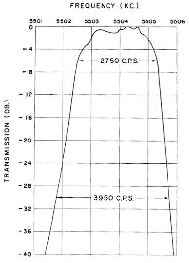
Fig. 11. Measured selectivity characteristic of the filter described in this article when aligned at 5505.2 kc. The 6 dB bandwidth is 2750 c.p.s., and the 30 dB/6 dB shape factor is 1.44.
The spurious crystal responses occur as indicated in Table 1, but the over-all filter exhibited more than 52 dB attenuation at the nearest spurious frequency (5516.800 kc). The others could not be measured since they were attenuated more than 60 dB, which attenuation level was beyond the capability of the measuring setup used.
It should be noted that this filter is better used to pass the lower sideband than the upper one. When aligned at the 5505.5 kc carrier frequency, the filter provides 20 dB of carrier attenuation with a 6 dB down audio pass band which extends from 300 to 2800 c.p.s. The undesired upper sideband is attenuated more than 40 dB for all audio frequencies above 350 c.p.s.
If the filter is aligned at 5505.2 kc and the carrier set at 5505.6 kc, carrier suppression is 19 dB for a 6 dB audio pass band of 300-3050 c.p.s. Upper sideband suppression is better than 40 dB for audio above 300 c.p.s.
The cutoff on the low-frequency side of the band is somewhat less steep than on the high side. This is believed to be due to the use of less than ideal coupling coils between the filter sections. Using an alignment frequency of 5505.5 kc and a carrier frequency of 5502.2 kc, the upper sideband audio pass band is 450-2950 c.p.s. for 20 dB carrier suppression. Undesired sideband attenuation is greater than 30 dB for audio above 350 c.p.s. and greater than 40 dB for audio above 750 c.p.s.
When the filter is aligned at 5505.2 kc and the carrier is placed at 5502.1 kc, the audio pass band is 400-3200 c.p.s. for 20 dB carrier attenuation. Lower sideband suppression will be more than 30 and 40 dB for audio frequencies above 300 and 700 c.p.s., respectively.
Appendix
The selectivity curves presented in this article were plotted from the equations below. All are in terms of the normalized frequency variable Z defined in the text.
The selectivity characteristic of the simple one-section (two crystals in a half lattice) filter is given on page 194 of Herzog.(13) In decibels this can be written.
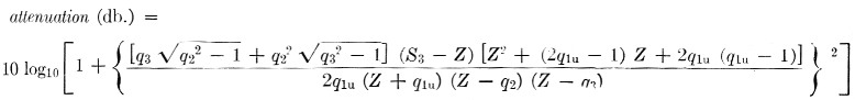
In this equation the q parameters correspond to the normalized frequencies at which infinite attenuation occurs. q1u is a normalized frequency below the pass band, while q2 and q3 correspond to frequencies which may be either below or above. S3 is a parameter which depends on q1u, q2 and q3. To obtain good rejection away from the pass band, the qs should be large. In particular, if q2 = ∞, and q3 = ∞, then S3 = 0. For the filter under consideration, q1u is the normalized frequency where infinite attenuation occurs due to the inductance used across the crystals. If q1u is also taken as infinite, the equation simplifies to attenuation (dB) = 10 log10 (1 + 4Z4).
The attenuation at Z = - 2 given by this equation is 18.1 dB. The attenuation computed from the more complicated expression for the same Z with q2 = q3 = ∞ and q1u = 294 (which corresponds to f∞ for the filter described in this article) is also 18.1 dB. Thus the effect of the added coils is trivial near the pass-band region.
If we assume that identical filter sections can be cascaded without affecting their basic selectivity characteristics: e.g., sections isolated with vacuum tubes to eliminate interaction due to mismatch, then two sections should produce the following response attenuation (dB) = 10 log10(1 + 4Z4)2 and three sections should have the characteristic attenuation (dB) = 10 log10(1 + 4Z4)3. These are the equations which are plotted in Fig. 7.
If an actual circuit employing cascaded identical filter sections is analyzed it is found that the expression for two sections is attenuation (dB) = 10 log10 [1 + 16Z4 (2Z2 - 1)2] and for three sections attenuation (dB) = 10 log10 [1 + 4Z4 (4Z - 1) (4Z2 - 3)2]. These selectivity characteristics are plotted in Fig. 8.
Three sections with the interaction of one section reduced yield the following characteristic attenuation (dB) ≈ 10 log10 [l + 16Z4 (2Z2 - 1)2] + 10 log10[1 + 4Z4]. This is plotted as Fig. 9.
Notes
- Weaver and Brown, "Crystal lattice filters for transmitting and receiving," QST, June and August, 1951.
- Good, "A crystal filter for phone reception," QST, October, 1951.
- Burns, "Sideband filters ysing crystals," QST, November, 1954.
- Morrison, "Cascaded half-lattice crystal filters for phone and c.w. reception," QST, May, 1954.
- Vester, "Surplus-crystal - high-frequency filters," QST, January, 1959.
- Vester, "Mobile s.s.b. transceiver," QST, June, 1959.
- Kosowsky, Patent No. 2,913,682.
- The classical method of filter design uses the notion of a characteristic impedance for a filter section. When several filter sections having the same characteristic impedance are cascaded, the over-all selectivity characteristic should be the product of the characteristics of the individual sections (or the sum of their responses in decibels). The difficulty is that the image impedance required to terminate the filter in its characteristic impedance is not realizable with ordinary resistive terminations. As a result, there is reflection at the termination which is a function of frequency, and the filter section does not provide the correct image impedance for an identical section which may precede it. In practical filters a match is obtained only on the average over the frequency range of interest. The input impedance, therefore, varies from the image impedance value, and it is this variation which causes a practical multisection filter to have a response which is different from that which would be expected from the characteristics of the individual sections.
- Shunt capacitance Co can be found using a Q meter or other standard capacitance-measuring technique. The transmission method described by Vester in QST for January, 1959, can be used to get the resonant frequency Jr. It is very difficult to get an accurate measure of f with this method because the null tends to be lost in the noise level of the equipment. To get around this, additional capacitance can be added across the crystal, moving the null in toward f where there will be more transmission on the high-frequency side. Motional capacitance C can then be calculated from the formula
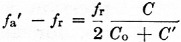
where fa' is the new antiresonant frequency with capacitance C' in parallel with the crystal, fr is the resonant frequency, and Co is the shunt capacitance of the crystal. The Co/C ratio is then calculated and substituted into the formula of Fig. 1 to find the fa - fr spacing. Actually, in designing filters similar to the ones. to be described, it is only necessary to make the relatively simple measurements of f and Co. The Co/C ratio can be taken as 4000 for FT-243 crystals in the 5500 kc region. - A simpler expression ban actually be used for the filter under consideration.
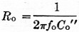 where fo is the center frequency of the filter, and Co" is the effective capacitance required (7.35 pF in this case) so that the correct fa - fr is exhibited by the crystal.
 - The input and output coils will have little effect on the impedance of the filter if 2πQfoL (or Q/2 foC) is large compared to Ro/2, Q and L are the Q and inductance of the coil, C is the, capacitance across the coil, fo is the center frequency and Ro/2 is the terminating resistance. This requirement is usually met in h.f. filters such as the one described. At lower frequencies such as 450 kc, the required Ro/2 is higher. Then the terminating resistor must be chosen so that it and the effective resistance of the coil in parallel will give the desired termination.
- Clark, "Hints & kinks," QST, December, 1959.
- Herzog, Siebschaltungen mit Schwingkristallen, Dietrich Press, 1949.
D.J. Healy, W3HEC.