The Gamma-matched ground plane
Simplified matching and construction for a popular antenna.
Matching a ground plane can be plenty of work with the methods usually employed, but this adaptation of the gamma match is both simple and effective. Also provided are complete construction details for 10, 15 and 20 meter ground planes with rigid radials.
The ground-plane antenna is a good low-angle radiator whose performance is relatively independent of where and how it is mounted. Getting a good match to a coaxial transmission line, however, is not always easy. Such practices as changing the droop of the radials, shortening (or lengthening) the vertical and adding inductance (or capacitance) undoubtedly work but are difficult. After all these methods, plus pi and L networks at the antenna, failed to match a 20-meter ground plane to better than a 1.5 s.w.r. (and by then bored with many week ends of up-the-tree adjustments), I decided to try one more thing before returning to the fondly-remembered Zepp.
The gamma match. It works wonderfully for beams - why wouldn't it work for a ground plane? It was simple enough to ground the vertical to the radials, run a No. 4 insulated wire parallel to the vertical and install a variable capacitor at the base of the wire. Then the antenna, although too short, was quickly matched to a low s.w.r. by adjusting the height of the connection between the wire and the vertical element and tuning out reactance with the capacitor. The antenna maintained this match for three years without any touching up.
Fig. 1 is a diagram of the ground plane and matching system. Fig. 2 shows s.w.r. vs. frequency curves obtained with the 20 meter antenna. Both a resistance bridge and a Mickey Match(1) were used for the measurements with almost identical results. Curve 2 in Fig. 2 is for the original shortened antenna. Curve 1 is for a vertical element of correct length, a recent improvement. I think you'll agree that a maximum s.w.r. of 1.3 across the entire 20 meter band is rather good. Without retuning the final, I can shift frequency from 14.00 to 14.35 Mc. with a maximum variation in final plate current of only 15 ma. from 330 at the center of the band.
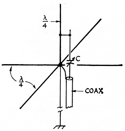
Fig. 1. Diagram of the gamma-matched ground plane. The vertical element and the radials are connected and grounded at the base. Matching is effected by adjusting the tap on the vertical along with capacitor C.
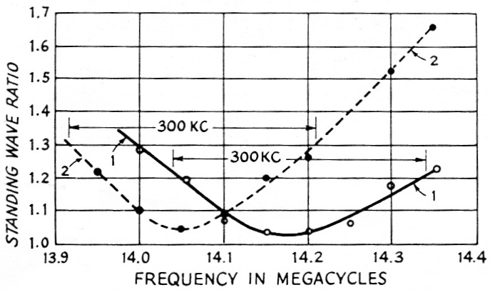
Fig. 2. S.w.r. vs. frequency characteristics of a 20 meter gamma-matched ground plane having a 2¼ × 3 inch downspout vertical element and 16.9 foot long, 0.84 inch diameter radials. No. 4 wire was used for the gamma rod. Data for curve 1 was taken with a 16.7 foot vertical element (the theoretically-correct length) and the gamma tap and capacitor adjusted for best match at 14.175 Mc. Curve 2 was made using a 16.0 foot vertical (too short) matched at 14.05 Mc. Note the higher minimum s.w.r. and the narrower s.w.r. bandwidth with the shorter element.
In the summer of 1959, after two solid weeks of adjustments on a three-band trap ground plane failed to even approximate the "typical s.w.r. curves" published by the manufacturer, I built a 15-meter gamma-matched ground plane. Matching again proved easy, and some of the resulting s.w.r. vs. frequency curves are shown in Fig. 3. A vertical of resonant length gave the lowest s.w.r. and the best band width. However, almost the same minimum s.w.r. and an s.w.r. of less than 1.4 across the whole band could be obtained with verticals up to 6 inches too long or too short by adjusting both gamma tap and capacitor. At the expense of a slightly higher s.w.r. and narrower impedance bandwidth, the frequency of minimum s.w.r. could be shifted by merely adjusting the capacitor.
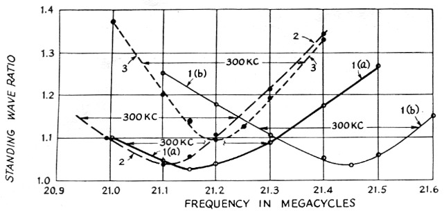
Fig. 3. S.w.r. vs. frequency characteristics of a 15 meter ground plane with 1¼ inch elements and a ¾ inch gamma rod.
For curve 1 (a), the elements were made the correct length (11.3 feet), and the gamma rod and capacitor were adjusted for best match at 21.15 Mc.
Curve 1(b) shows the performance of the same antenna when only the capacitor was used to shift the frequency of best match to 21.45 Mc. Note the slightly higher minimum s.w.r. and the higher s.w.r. over a 300 kc band width.
Curve 2 shows what happened when the elements were made too long (11.86 feet), and the matching system was adjusted at 21.10 Mc. Both minimum s.w.r. and s.w.r. bandwidth are worse than in curve 1(a). This is also true of curve 3, taken with short elements (10.2 feet) adjusted for best match at 21.20 Mc.
Some ground-plane users have suggested that the radials be made from 2½ to 12 per cent longer than the vertical, and I have used the first figure with good results. However, the radial length has proven experimentally to be even less critical than the length of the vertical. My recommendation is not to fuss with element lengths but just make all five a quarter-wavelength long at the band center (allowing for their diameters as shown in the Antenna Book) and let the gamma match do the rest.
The gamma-matcned ground plane has another advantage over the usual model besides ease of adjustment. Construction is easier since there is no need- to insulate the base of the vertical from the radials. Indeed, the vertical can be a continuation of the supporting mast. The entire assembly can be solidly grounded for lightning protection. Experiments with both antennas showed that when they were gamma-matched without a ground connection, no change occurred when a ground was added. (Use a ground rod of the same metal as the one at the transmitter or electrolytic action will cause a current through the coax sheath that connects the two.)
Construction
Fig. 4 shows the construction recommended for a 10, 15 or 20 meter ground plane. This design is very much like my 15 meter antenna, but embodies a few afterthoughts to make inthe-air assembly easier. The vertical and the radials are made of 1¼ inch aluminum tubing slipped over shorter lengths of standard ¾ inch steel pipe. The pipe greatly reinforces the tubing at points of maximum bending moment and also prevents clamps and bolts from collapsing the tubing. Don't substitute rigid conduit; it has a thinner wall than pipe and it has threads with a different taper (same threads per inch, however) which do not fit the pipe crosses as well. The - aluminum tubing is available at many radio stores in 12 foot lengths. This is long enough for 10 and 15 meter elements, and 1_1/8 inch aluminum tubing extensions can be added for 20 meter.
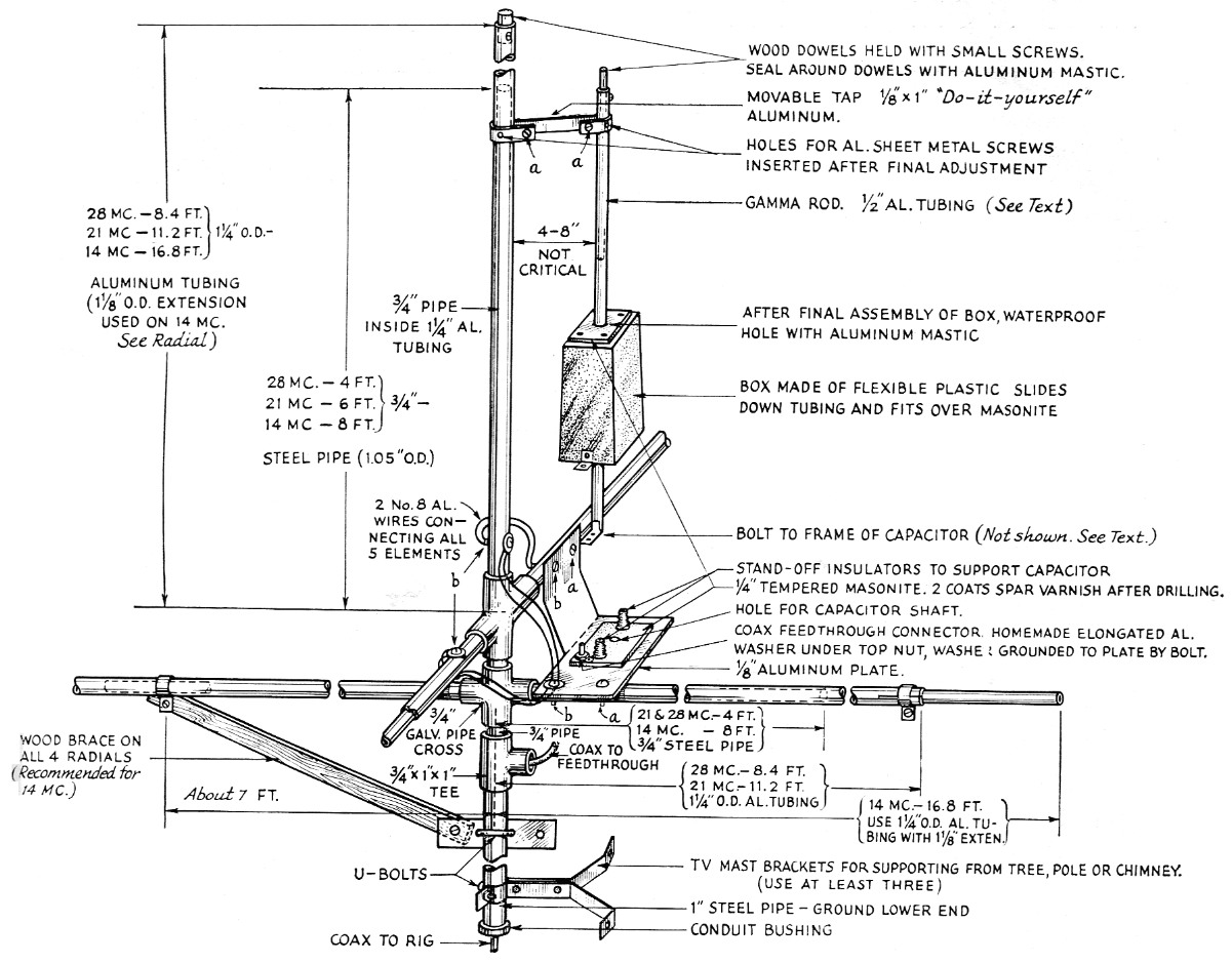
Fig. 4. Construction details for the gamma matched ground plane with dimensions for 10, 15 and 20 meter (28.5, 21.2 and 14.17 Mc). The basic framework is made of steel pipe fastened together with two pipe crosses and a tee fitting. 1¼ inch aluminum tubing elements slip over the pipes and are fastened in place by bolts which also hold wires to bond the elements together. Fastenings marked "a" are ¼ × 1½ inch "do-it-yourself" aluminum bolts; those marked "b" are ¼ × 2 inch steel bolts equipped with two large aluminum washers.
Aluminum bolts should be used so far as possible since they don't rust or cause galvanic action. Where steel bolts are used, seal the nut with aluminum mastic (sold for sealing joints in aluminum gutters) so that the nut may be removed later without drastic action. Galvanized bolts seem to last all of six months before rusting; better weatherproof them with mastic, also.
The variable capacitor should be double spaced, not for electrical reasons but to prevent shorting by condensation, as is likely to happen if the capacitor is mounted with its shaft vertical. A maximum capacitance of 100 pF for 20 and 15 meters and 50 pF for 10 meters should be ample. Use a soft plastic box for the rain shield - the hard ones will crack. I used an automobile wastebasket about 3 by 8 by 12 inch high, which is more than adequate in size. Use of a coax feedthrough connector rather than a jack prevents any water that leaks into the box from shorting the transmission line.
The length of the gamma rod will be between 1/6 and 1/3 the height of the vertical radiator if 52 ohm coax is used. Of course, the smaller the rod and the greater the spacing from the radiator, the greater will be the impedance transformation for any given tap height. Experiments showed that ½ inch diameter rod would always provide a match while No. 8 aluminum wire did not always match with a reasonable spacing. In any event, the rod should be used for mechanical ruggedness, and any spacing from 3 to 12 inches will probably work.
To prevent oxidation, the aluminum elements should have at least one coat of spar varnish - except, of course, where the gamma tap is expected - before erection. It is suggested that marks 1 inch apart be filed on the gamma rod with double marks at integral feet from the radials. These marks will be very useful when the matching is done.
Matching
Don't try to check antenna resonance with a grid-dip oscillator. By adjusting the gamma capacitor you can get dips over a wide range of frequency, and the "best" dips won't even approximate the final matching adjustment.
Hook up an s.w.r. bridge at the transmitter end of the coax, and excite it with a low-powered transmitter tuned to the center of the band. Don't try to use the unstable, inadequately-powered g.d.o. for this purpose, either. With a helper at the s.w.r. meter and you up in the air, start with a tap that you think is too higher too low and adjust the gamma capacitor for minimum s.w.r. Then move the tap an inch at a time (with the transmitter turned off), each time adjusting the capacitor. The s.w.r. should drop progressively lower and then start to rise. Try tap positions ¼ inch apart in the region of minimum s.w.r. A position should be found where the meter reads practically zero. The tap height and capacitor settings are quite critical, but the process of finding them is straightforward and easy.
Now tune the transmitter across the band. If the s.w.r. is considerably higher at one edge than the other, the frequency of minimum s.w.r. can be shifted by tuning the capacitor without having to adjust the tap. With some rod spacings and tap heights you may have to decrease the capacitance to shift to a lower frequency. This sounds wrong but can probably be explained as follows: The gamma section is a transmission line less than a quarter wavelength long, terminated in an impedance less than its characteristic impedance. At lower frequencies the antenna and the gamma section are electrically shorter. As the frequency is reduced the antenna will reflect increasing capacitive reactance through the section, and the section itself will have decreasing inductive reactance. One would expect that more gamma capacitance (less capacitive reactance) would be required to establish resonance. But, at lower frequencies the radiation resistance of the antenna also drops, and this tends to increase the inductive reactance seen at the input of the gamma section. Depending on the impedances of the gamma section and the antenna, this effect may outweigh the expected behavior, and more capacitive reactance (less capacitance) will be required for resonance.
Other experiments showed that elements shorter than the resonant length required a higher gamma tap and less capacitance for optimum matching. The opposite was true with long elements. This agrees with Nose's results using a gamma-matched beam.(2) The shorter elements have lower radiation resistance and require a higher tap for the desired 52 ohms. The
(Continued on page 144)
Notes
- Bunco, "The 'Mickey match'," QST, November, 1958.
- Nose, "Notes on parasitic beams," QST, March, 1960.
Benson Boss, K2GHM/W3DAZ.