More on homemade transformer design
General procedure for constructing high-voltage units.
This article was originally submitted as a letter for the Technical Correspondence section of QST in response to an article by Robert Coats in the September 1959 issue. However, the editors felt that the broader treatment by W2VLA warranted its presentation as a regular article. The author wishes to emphasize the fact that this material was inspired by the previous article by W9ESD.
Thanks to W9ESD, today's radio amateurs have been introduced to the art of simplified transformer design.(1) His design method and fabrication technique clearly illustrate the relative simplicity of high-voltage transformer construction. Strangely, however, very few people, including engineers, consider themselves adequately equipped to undertake a transformer design job. The reason for this is perhaps due to the fact that the criteria for efficient and economical transformer design have not been clearly established. If cost, minimum weight and minimum volume are not the primary controlling design factors, a simple and conservative step-by-step design procedure can be easily formulated. The author, no expert in the field of transformer design, has recently been required to design and construct small power transformers for developmental airborne electronic equipment. In becoming familiar with the various design parameters, a simple but effective design procedure has evolved. This procedure, while not optimum in the sense of minimum cost, weight and volume, has proven quite satisfactory in the design of those transformers needed for experimental evaluation.
Core material
At the outset, several design parameters are usually known. These are:
- Line voltage in volt.
- Frequency in cycles per second.
- Load power or volt-ampere.
- Core material, its normal flux density and stacking factor.
The radio amateur is quite familiar with the first three parameters. In selecting suitable core material, consideration should be given to the peak flux density, exciting current, the ease of applying the windings and the core cost. The best core materials are usually characterized by high peak flux densities and small exciting currents. Grain-oriented silicon steel has few superiors. It is perhaps just as easy to apply the windings to a core consisting of iron laminations as it is to the C core described by Coats. However, when a C core is purchased one does not have to worry about having too many or too few laminations to make up the desired core. Also, the stacking factor, which is the ratio of iron volume to total core volume, is controlled by the manufacturer and is normally as high as practical. As Coats points out, the stacking factor for 12 mil C cores is approximately 95 per cent. The cost of C cores, especially the standard sizes, seems to be quite reasonable.
The grain-oriented silicon-steel C core is available in various sizes from a number of manufacturers, notably the Arnold Engineering Company and the Westinghouse Electric Company. The Arnold trade name is Silectron and the various core sizes are described in their Bulletin SC-107A. The Westinghouse trade name is Hipersil. The descriptive bulletin covering these cores is 44-550. Curiously, the AA-520 C core used by Coats is not a standard size. The next larger core size, AA-523, is less expensive by approximately $1.50 and is a standard core size. The Westinghouse catalog lists an A-520 core which is exactly equivalent to the AA-520 but it, too, is not a standard core size. From the consideration of cost and availability (standard core sizes are usually stocked) the designer should endeavor to use only standard sizes whenever possible.
Core size
Proceeding now to the step-by-step procedure for transformer design, it is first necessary to compute the r.m.s. primary and secondary currents. This can be found from the formula
Next, a wire size is selected that will carry the primary current without excessive heating. This can be done by referring to the accompanying table which lists the various wire sizes, the wire area in circular mils (including insulation) and the current-carrying capacity based on 1000 c.m. /ampere. As Coats has stated, allowing one circular mil of copper for each milliampere of current is a conservative design consideration.
The next step in the design is to estimate the winding-space factor, K. This factor is the ratio of the total wire area threaded through the core window to the area of the window itself. For a scramble-wound two-winding transformer the winding-space factor of either the primary or secondary (their areas are usually approximately equal) rarely exceeds 20 per cent of the total window area. For high-voltage transformers, where extra layers of insulation must be applied to prevent voltage breakdown, the winding-space factor for each winding may be less than 10 per cent. The designer's ability to fill the core window with as much copper as possible is a direct measure of his transformer winding proficiency.
When the winding-space factor, K, has been chosen the designer can compute the WA product,
![]()
where:
W is the window area in square inches,
A is the nominal cross-sectional core area in square inches,
E is the r.m.s. line voltage in volts,
Aw is the cross-sectional area of one turn of primary wire in circular mils, including insulation,
S is the stacking factor of the core material, K is the winding-space factor,
f is the frequency in cycles per second, and
BM is the peak flux density in gausses.
For Silectron and Hipersil the WA product times 50 is the approximate maximum power in watts that a core can handle under normal conditions at 60 c.p.s. and 15,000 gausses.(3) The Arnold Engineering catalog lists C cores by increasing order of WA product.(4) The Westinghouse catalog does not observe this convenient convention. Knowing the computed WA product, the designer merely enters the catalog at the appropriate place and selects a core whose WA product, appropriately multiplied, equals or slightly exceeds the desired power rating, keeping in mind that it is economically advantageous to select a standard core size.
Windings
Once the core has been selected, the design proceeds rapidly. As Coats has stated, the number of primary turns is determined from the formula:
![]()
The number of secondary turns is then computed from the formula:
![]()
It may be desirable to multiply the number of secondary turns by 1.05 or 1.10 to allow for the transformer regulation.
The primary and secondary wire sizes that will fit in the core window can now be computed from the formulas:
![]()
and
![]()
where Awp and Aws are the circular-mil areas (including insulation) of the largest size wire of primary and secondary, respectively, that can be accommodated by a window whose area in square inches is(5) W.
As was mentioned before, the choice of K will depend on the type of transformer being fabricated and the ability of the builder to fill the window with as much wire as possible. For low-voltage transformers, where the peak voltage between windings does not exceed approximately 500 volt, the winding-space factor may be chosen as 0.2. In doing so, however, the coil bobbins should be made of relatively thin material and fit the core quite closely. (A method of bobbin fabrication which does not require two material thicknesses is included in the latter part of this article.) The total space factor, KT, is given by
![]()
It is the ratio of the total wire area, both primary and secondary, to the window area and in practice rarely exceeds 0.4 for scramble-wound coils. For high-voltage transformers, the total winding-space factor KT should be chosen as 0.2 or even smaller. This will allow plenty of area for the generous application of high-voltage insulating materials. It should be noted that if the proper winding-space factor is used in determining the WA product, the area of the primary wire just computed will agree closely with the primary-wire area selected at the beginning of the design procedure. When applying the windings to the core, half the number of turns of each winding should be wound on each core leg. This maximizes the coupling between primary and secondary and improves voltage regulation.
Example
To illustrate the design method, consider the following example for the design of a high-voltage plate transformer.
The primary voltage is 115 volts. The secondary voltage is 3000 volts. The frequency is 60 c.p.s. The load power is approximately 1200 watt. It is arbitrarily decided to use a Hipersil or Silectron 12-mil core whose stocking factor is 0.95 and whose normal flux density is 15,000 gausses.
First the primary and secondary currents are computed.
Note that twice the output voltage was used in the calculation of the secondary current. The secondary will be center-tapped for full-wave rectifier operation.
Next, reference is made to the wire table. This table is entered where No. 10 Heavy Formvar is chosen for the primary wire. This wire has a cross-sectional area of 11,130 c.m. As this is a two-winding high-voltage transformer the winding-space factor, K, is chosen to be 0.1. Since the maxiinum primary or secondary space factor for the wire of a two-winding transformer is approximately 0.2, the choice of the 0.1 winding-space factor should allocate sufficient space for all of the high-voltage insulation necessary.
Using formula (2) the WA product is computed.
![]()
Entering the Arnold Engineering Bulletin SC-107A, page 30, it is apparent that the AA-517 core is the smallest core that meets our design criteria. Selection of the next largest standard core size, AA-518, will permit extra power to be designed into the transformer and will cost less than the AA-517. Fifty times the computed AA-518 WA product is almost 2100 watt(6) so the design is indeed conservative. If the designer becomes expert at filling the core window with wire, smaller core sizes may be selected.
The nominal cross-sectional area, A, of the AA-518 core is 3.81 square inches. The window area, W, is 10.9 square inch.
The number of primary turns is computed from formula (3):
![]()
and the number of secondary turns can be computed from formula (3):
![]()
The number of secondary turns is multiplied by 1.05 to allow for the transformer regulation. This gives a total number of secondary turns of 6700.
Now that we know the number of turns required, we can check back to see how much area the core window allows for each turn with a K factor of 0.1.
Using equations (5) and (6),
![]()
| Wire Size (A.W.G.) | Wire Area (Cir. Mils) (Heavy Formvar) | Current Capacity (mA) |
|---|---|---|
| 40 | 14.4 | 9.61 |
| 39 | 17.6 | 12.25 |
| 38 | 23.0 | 16.00 |
| 37 | 29.1 | 20.25 |
| 36 | 36.0 | 25.00 |
| 35 | 44.9 | 31.36 |
| 34 | 56.2 | 39.69 |
| 33 | 70.5 | 50.41 |
| 32 | 88.3 | 64.00 |
| 31 | 108.0 | 79.21 |
| 30 | 134 | 100.8 |
| 29 | 169 | 127.6 |
| 28 | 207 | 158.8 |
| 27 | 259 | 201.4 |
| 26 | 320 | 252.7 |
| 25 | 400 | 320.0 |
| 24 | 497 | 404.8 |
| 23 | 620 | 510.0 |
| 22 | 767 | 640.3 |
| 21 | 961 | 812.1 |
| 20 | 1147 | 1024 |
| 19 | 1489 | 1289 |
| 18 | 1888 | 1624 |
| 17 | 2323 | 2052 |
| 16 | 2894 | 2581 |
| 15 | 3624 | 3260 |
| 14 | 4529 | 4109 |
| 13 | 5670 | 5184 |
| 12 | 7088 | 6529 |
| 11 | 8873 | 8226 |
| 10 | 11,130 | 10,300 |
| 9 | 13,950 | 13,090 |
| 8 | 17,530 | 16,510 |
![]()
The computed primary-wire area exceeds the wire area of No. 10 wire, proving the choice of this wire size is satisfactory. The wire area of the secondary winding corresponds to No. 28 wire, whose current-carrying capacity, based on our conservative estimate of 1 circular mil per milliampere, is only 158.8 milliamperes. By selecting the next larger size, No. 27, the wire size requirement for the secondary current is adequately satisfied.
As a check, it is advisable to compute the total space factor, KT, using equation (7).
![]()
This space factor does not seem unreasonable, since it is much less than 0.4. If there are any doubts in the designer's mind, he may choose the next larger standard core size, AA-533. Usually, however, total winding-space factors up to 0.3 are easily accommodated, except in cases where excessive insulation is used or windings are not well fitted.
Making the secondary windings
There are several practical suggestions which the writer feels may be useful to the inexperienced transformer designer. Fig. 1 illustrates the construction of a coil bobbin which does not require the use of screws or other fasteners. The bobbin tube is made from four pieces of thin Formica or Textolite, two pieces of which have small ears. The purpose of the ears is to prevent the bobbin flanges from separating from the bobbin tube. If the parts are accurately dimensioned, the bobbin will be almost self-supporting or can be tacked with varnish or glue. The bobbin should fit snugly to the core in order to conserve winding space. The material thickness should be as thin as strength will allow.
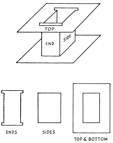
Fig. 1. Sketch showing the self-supporting bobbin described in the text. It should fit the core leg snugly. The top and bottom flanges should have such a width that they extend halfway across the core window opening.
In winding the secondary pies, the writer recommends the fixture in Fig. 2. After the primary winding has been applied to the bobbins, the dimensions of the quadrilateral formed by the four screws can be determined by measurement. If the plate is drilled and tapped at the appropriate places, allowing some room for the insulation wrap, snug-fitting secondary pies can be easily fabricated. As a rule of thumb, the number of turns on each pie can be determined by dividing the total secondary voltare, by 500 and rounding the result off to the nearest even integer. Then, the number of secondary turns per pie are determined by dividing the total secondary turns by the number of pies. The thickness of the pie winding must be checked to make sure that it does not exceed one-half of the window height remaining after the primary winding is applied. In other words, the pies should not protrude outside the bobbin.
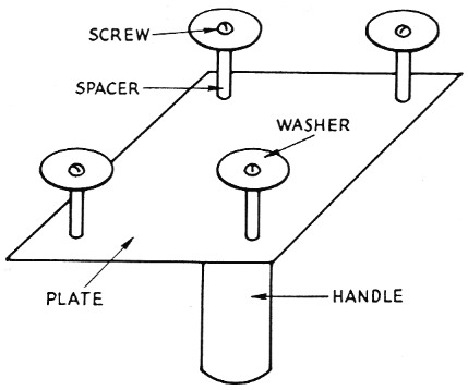
Fig. 2. Tool suggested for winding the secondary pies. The corner posts around which the wire is wound should be spaced so that the finished pie will fit snugly on the bobbin.
Finishing
To conserve winding space, it is important that the rectangular cross section of the pies be maintained after wrapping. To do this, the bare pie should be soaked with a thin varnish or perhaps an acrylic aerosol spray and then allowed to dry before removal from the pie-winding tool. If carefully handled after removal, the pie should maintain its rectangular cross section during the wrapping operation. To further stiffen the pie assembly the wrapping material should be painted with a good grade of insulating varnish. To prevent the bare pie from sticking to the tool, coat the tool with a thin coat of paraffin or spray it with one of the liquid wax aerosols.(7)
A superior pie-wrapping tape is Scotch X-1045 thermosetting electrical tape, which can be baked to a rugged fused coil encapsulation in the kitchen oven. This tape is available directly from the Minnesota Mining & Mfg. Co. in several convenient widths. Suspend the coil by its leads, if possible, and cure for two hours at 250° F. Keep the starting and finishing wires well separated.
Banding
Perhaps the most difficult task facing the amateur transformer constructor is that of adequately banding the core. While TV chimney mounts, pipe straps and adjustable hose clamps may be satisfactory for the job, one should not overlook the possibility of taking the assembled core and coil to a local transformer manufacturer or power company. It is quite possible that these organizations will have the banding straps and banding tool necessary for the job.(8) In addition to the mounting plate illustrated by Coats, a second metal plate banded to the top of the transformer makes a convenient terminal board. Primary and secondary wires can be brought to feed-throughs in this plate. The plate may be either flat or L-shaped depending on whether the terminals are desired at the top or side of the finished transformer.
The ingenious high-power enthusiast can probably save a considerable sum of money constructing high-voltage transformers by the methods ..........
Notes
- Coats, "A cool kilowatt plate transformer," QST, September, 1959. This article should be used as a reference for several of the points discussed here.
- This simplified relationship does not include the considerations of power factor and transformer efficiency, both of which will tend to increase primary and secondary currents above the values calculated here. However, the conservative choice of wire size should provide sufficient tolerance. Calculations assume a full-wave rectifier and choke-input filter.
- The Arnold Engineering bulletin specified a factor of 100 instead of 50 but refers this to a shell-type transformer employing two C-type cores of the type number listed. For the core-type transformer described here, the factor should be 50.
- The actual WA product is not given in the Arnold catalog, but is readily obtainable by multiplying together the figures for "Gross Area" and "Window Area." - Ed.
- Square inches may be converted to circular mils by multiplying by 1.275 × 10⁶.
- Computed as follows: (50) (10.9) (3.81) = 2080 watt. The figure of 4150 watt shown in the Arnold catalog must be modified as mentioned in Footnote 3.
- Experimental development of the pie winding, stiffening and wrapping techniques is credited to Mr. Robert Riker.
- For preliminary transformer testing, the core may be secured with a C clamp, carpenter's clamp, or vise.
T.J. Maresca, W2VLA.