Multiband antennas using decoupling stubs
Substituting transmission line sections for lumped-constant traps.
Since W4JRW obtained a patent on this multi frequency antenna system nearly ten years ago we can't call it "new," but at least it should be welcome news to those seeking a simple way to get good radiation on several bands. Shorted 1/4-wavelength stubs provide r.f. insulation and also serve as part of the antenna.
Since amateurs usually desire to operate on more than one band, several methods have been devised to use a single antenna on several bands. The earliest arrangements employed various combinations of feeder lengths, antenna lengths, and series or parallel tuning of the coupling circuit. Later on, the use of parallel-tuned "traps" with lumped constants which act as insulators at a particular frequency was invented.(1) A practical arrangement of this system for amateur use was developed(2) and is in rather wide use.
It is well known that the parallel-tuned circuit and quarter-wavelength shorted stub of Fig. 1 are very similar electrically. Both configurations show a high impedance across points A and B. However, if a stub is connected to an antenna in this manner it does not act as an insulator but rather as a phase changer. The collinear antenna uses such stubs to operate a series of halfwave sections in phase.
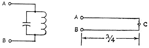
Fig. 1. A parallel-tuned circuit has a high impedance at its resonant frequency, and so does a ¾ wavelength shorted transmission line.
There is a different connection possible for the stub, that is from A to C, which will result in insulator action or decoupling in an antenna.(3) For instance, shorted stubs a quarter wavelength long at 28 Mc can be attached to the ends of a 28 Mc dipole as in Fig. 2. The 28 Mc dipole is effectively isolated or decoupled from the balance of the antenna which can be made long enough to resonate at 14, 7 or 3.5 Mc. If another pair of stubs is added for 14 Mc, there will be isolation at both 28 and 14 Mc, and a 10-20-40-meter or 10-20-80-meter antenna can be made.
The stubs can be made of open-wire line, Twin-Lead, or coax. Their lengths can be found from the formula
![]()
The over-all length of an antenna containing decoupling stubs will be somewhat less than the figure given by the usual formula for a half-wavelength dipole - Length (feet) = 468/Frequency (Mc). For instance, an antenna for 10 and 20 meter must be 29 feet, 10 inch long for resonance at the lower frequency, whereas the formula gives a length of 33 feet.
If open line with a velocity factor of nearly unity is used for the stubs, the over-all length of a two-band antenna would be nearly a full free-space wavelength at the higher frequency and the whole antenna would resonate at something less than half that frequency. Very fortunately, the velocity factor of 300 ohm tubular Twin-Lead (0.8) gives such lengths for the stubs that, in most cases, adding the stub makes the antenna resonate at just half the original frequency.
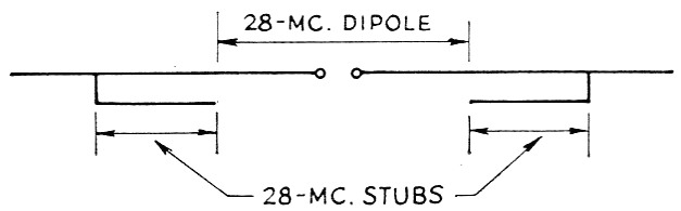
Fig. 2. A two-band antenna for 28 Mc. and some lower frequency. The center portion is an ordinary 10 meter dipole. The shorted stubs are ¼ wavelength long at 28 Mc and look like an open circuit at that frequency when connected to the dipole as shown. Extensions on the ends of the stubs can be used to resonate the antenna at any frequency less than half of 28 Mc.
Fig. 3 shows how tubular Twin-Lead can be used for the antenna itself as well as the stubs and includes dimensions for 10 and 20 meter operation. The foam-filled type of Twin-Lead is recommended to keep out moisture.
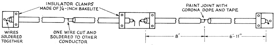
Fig. 3. Construction and dimensions of an antenna for 10 and 20 meters using 300-ohm tubular Twin-Lead for both the dipole and stubs. Either a 50- or 75-ohm transmission line can be connected at the center of the dipole.
Lengths for three and four band antennas using the same construction are given in Fig. 4.
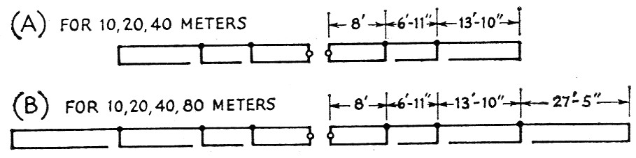
Fig. 4. Dimensions of stub-decoupled antennas for 10, 20 and 40 meters and 10, 20, 40 and 80 meters made of tubular Twin-Lead. Either antenna can also be used on 15 meters where the 40-meter section is ¾ wavelength long.
Fig. 5 indicates the standing-wave ratios observed across various bands when these antennas were fed with 50 ohm coax.
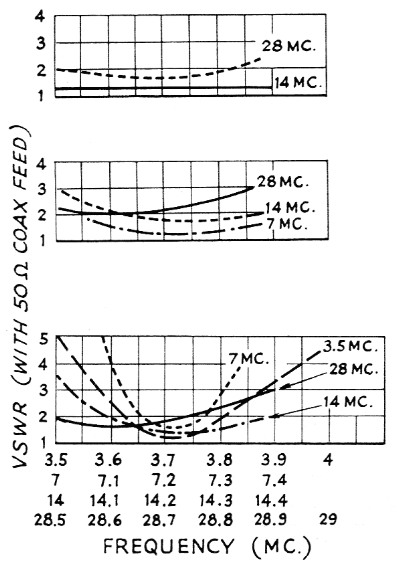
Fig. 5. From top to bottom, s.w.r. characteristics of the antennas shown in Figs. 3, 4A and 4B. A 50 ohm coaxial transmission line was used, and the measurements were made with a Micromatch.
The antenna of Fig. 6 can be used when only 40- and 80-meter operation is desired. Since the 40 meter portion is not made up of stubs it must be longer than the antenna of Fig. 4A. However, the isolating stubs must still be 3 wavelength long (allowing for velocity factor), and the whole antenna would resonate at a frequency below 3.5 Mc if the stubs were simply added to the ends of the 7 Mc dipole. To get around this, the dipole is shortened until the whole antenna tunes to 80 meters. Then resonance at 40 meters is restored by adding extra lengths of wire at the stub junctions. These wires are short and can just hang down from the antenna as shown.
Any of the antennas which will operate on 40 meters can be used on 15 meters as the 40-meter stubs will be approximately ¾ wavelength long and will provide decoupling. The result is equivalent to operating a 7 Mc dipole at three times its resonant frequency, and we have found the s.w.r. is usually not lower than 3 to 6 when using 40 meter antennas of any type on 15 meter.4
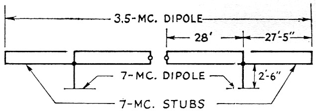
Fig. 6. A stub-decoupled antenna for 40 and 80 meter. In this case wires must be hung from the ends of the 40 meter dipole to resonate the antenna in that band.
The power rating of the antenna will depend on the insulation at the stub junctions. These junctions can be painted with corona dope and covered with vinyl tape. It has been our experience over several years that the insulation will not break down with a kilowatt-input transmitter, 100 per cent modulated, except when wet or very damp. In this case, the input should be reduced to perhaps 500 watts unless special precautions have been taken to seal up the junctions at the open ends of the stub. Of course, on the lowest band for which the antenna is designed the stubs do not have voltage across them and will not be subject to breakdown or flashover. The high voltage across the open end of a stub occurs only at the resonant frequency of that stub.
Fig. 7 shows the constriction of several 10 and 20 meter antennas which have been built and the dimensions required for resonance in these bands. The spacing between the rods forming the shorted stubs is not critical - the same lengths were obtained with 1-inch instead of M-inch spacing. Tnsulators should be made of low-loss material. Reflectors and directors for a multiband beam could be made up the same way.
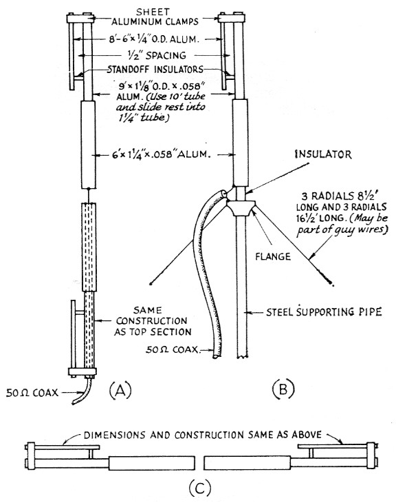
Fig. 7. Dimensions and suggested construction for coaxial, ground-plane and tubing dipole antennas for 10 and 20 meter. The arrangement in A might be mounted with standoff insulators attached to the 1¼ inch sections near the center of the antenna. The dipole in C could be closed at the center and fed with a gamma or "T"-matching system. Similarly-constructed parasitic elements could be added to make a multiband beam.
Notes
- Morgan, "A muitifrequency tuned antenna system," Electronics, August, 1940.
- Buchanan, "The multimatch antenna system," QST, March, 1955.
- Lattin, Patent No. 2,535,298.
- Theoretically, a center-fed antenna working on its third harmonic shouldn't be more than about 50 per cent higher in resistance than on the fundamental. One would expect an s.w.r. on the order of 2 to 1 rather than such high figures. - Ed.
William J. Lattin, W4JRW.