Using the 7360 in the HBR-16
Beam deflection tube for improved product detection.
The use of a 7360 beam-deflection tube in the HBR-16 receiver results in a much improved product detector for the reception of sideband signals. The 7360 detector circuit not only provides greater audio output voltage and much lower intermodulation distortion, but also adds the feature of impulse noise limiting. The circuit is so designed that tube replacement does not require adjustment of element voltage.
Although pentagrid converters are basically product-detection devices, they have some inherent limitations. Characteristics of the pentagrid-converter tube are such that small changes in element voltages can shift tube operation out of the "center of the linear range" under large-signal conditions. The pentagrid product detector shown in Fig. 1, for example, has the carrier-insertion signal applied to grid No. 1 and the modulated sideband signal to grid No. 3. Because of the electronic interaction existing between grid No. 1 and grid No. 3, pentagrid converter tubes are seldom used to generate their own beat-frequency-oscillator signals in productdetector circuits.
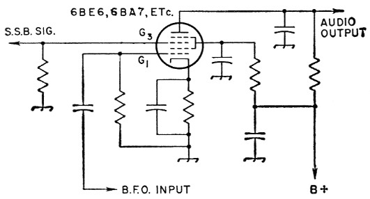
Fig. 1. Pentagrid product-detector circuit.
A second method of product detection; i.e., the popular Crosby system,(1) uses two dual-triode units which require additional socket space and components. The limitations of both systems can be circumvented by the use of the 7360 beam-deflection tube.
Features of the 7360
The 7360 is a grid-controlled beam-deflection tube having a cathode, control grid, screen grid, two deflecting electrodes, and two plates in a nine-pin miniature envelope. The tube was specifically designed for application in such sideband circuits as balanced modulators, balanced mixers, product detectors, and frequency converters.(2)
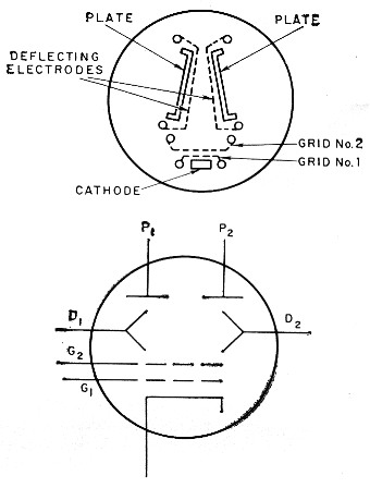
Fig. 2. Sketches showing the mechanical arrangement d electrodes in the 7360 and equivalent circuit symbol.
The tube structure, shown in Fig. 2, is such that the total beam current is determined by the voltage applied to grid No. 1 and grid No. 2. The difference in voltage between the deflecting electrodes determines the amount of beam current collected by each plate. In balanced operation, the beam current is divided equally between the two plates. When signals are applied to grid No. 1 and one of the deflecting electrodes, the resultant output contains signal components produced by the product of the input signals. Therefore, if the modulated signal is applied to one of the deflecting electrodes and the carrier insertion is applied to grid No. 1, the resultant output contains the desired audio component.
Receiver modification
The October 1959 issue of QST presented an excellent article by W6TC on the HBR-16 receiver.3 Because the pentagrid converter origirally used for product detection in my own home-brew" HBR-16 left much to be desired strong signals produced distortion), conversion to he 7360 for product detection seemed worthwhile. The incorporation of the 7360 into the HBR-16 required several modifications of the original circuit shown in Fig. 3. The seven-contact socket formerly occupied by the 6BE6 (V9) was removed and replaced with a shielded nine-contact socket. All circuit components between the two sections of the a.m./s.s.b. switch (S7) were removed. The r.f. filter network, consisting of a 5600 ohm resistor and two 250 pF capacitors, was left untouched. The bottom end of the second i.f. transformer (T4) secondary was lifted from ground and connected as shown in Fig. 4. (Good wiring technique is essential here because of the limited space available.) Because this connection places approximately 35 volt d.c. on the secondary of T4, a 0.1 µF capacitor, C1, was placed between the a.m. position of switch 437A and the infinite-impedance detector grid (V1OA). A 1-megohm resistor was also added from grid to ground on VISA. It was necessary to repeak T4 for `maximum gain after the conversion was corn pleted. It was noted that the secondary of T4 exhibited a sharper peak when tuned; in the original circuit, the tuning was much broader.
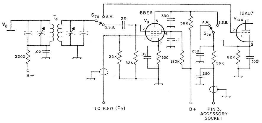
Fig. 3. Product-detector circuit used in the original HBR-16 receiver. (Values are revised as per QST for April, 1960.)
The b.f.o. output-coupling capacitor, Cs, was adjusted to bring the voltage up to 10 volts peak-to-peak on grid No. 1 of the 7360. Investigation of the particular b.f.o. circuit used in the HBR-16 indicated an output r.f. voltage slightly over 10 volts peak-to-peak. This adjustment is preferably made with the aid of an oscilloscope. If a scope is not available, Cs may be adjusted for maximum undistorted audio-output signal. This value will be a little less than maximum capacitance.
Performance
A quick operating check of the completed circuit is simple to perform. Turn on the receiver and place the a.m./s.s.b. switch in the s.s.b. position with the b.f.o. on. Tune in an s.s.b. signal and adjust the b.f.o. for clear reception. Switching off the b.f.o. at this point should result in negligible audio at the speaker. (Because of the good isolation between the two signal elements. interaction is negligible_)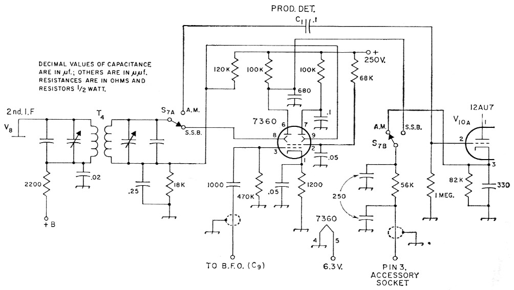
Fig. 4. Diagram showing circuit and connections for substituting a 7360 in the product tector of the HBR-16. See text referring to C1; other component designations refer to original circuit.
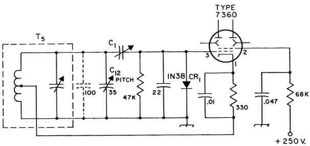
Fig. 5. B.f.o. circuit for self excitation. Decimal values of capacitance are in µF; others in pF. Resistances are in ohms and resistors ½ watt.
| C1 | 30 pF ceramic or mica trimmer. |
| C12 | See original b.f.o. circuit. |
| CR1 | 1N38 germanium diode. |
| T5 | See original b.f.o. circuit. |
Self Excitation
If desired, the 7360 may be used to provide its own b.f.o. excitation, thus eliminating the need for the separate 6B116 b.f.o. tube, V11. The author used this method of excitation in his final revision and the circuit is shown in Fig. 5. C1 is used to adjust the signal level on grid No. 1 to a value of from 5 to 10 volts peak-to-peak with respect to the cathode. This adjustment shifts the b.f.o. frequency somewhat, but the shift can be compensated for by adjustment of the capacitor in T5. The pitch control C12 is the frontpanel control and is used to zero beat the incoming signal. The 100 pF capacitor shown in dotted lines was required to provide adjustment to zero beat but may not be required in all instances. The grid-clamping diode CRr prevents the No. 1 grid from approaching too closely to zero voltage, at which point distortion would result. Using this arrangement in my receiver, the stray coupling to the deflecting electrodes was in the order of 25 dB below the normal peak-signal level. Because the detector conversion gain of the 7360 in the product-detector circuit is about 6, the audio-output stage can be driven directly in most cases.
Noise limiting
Another feature of the 7360 is its excellent noise-limiting capabilities. The normal signal voltage appearing at the deflecting electrodes should be limited to a maximum value of 8 volts peak-to-peak. If this voltage becomes larger, the audio signal becomes slightly clipped. Noise pulses ten times greater than the s.s.b. signal were only twice the peak audio signal after detection. It is recommended that the deflecting-electrode signal be kept near the maximum of 8 volts peak-to-peak to take advantage of this signal-limiting feature. The signal-limiting characteristics of the 7360 are shown in Fig. 6.
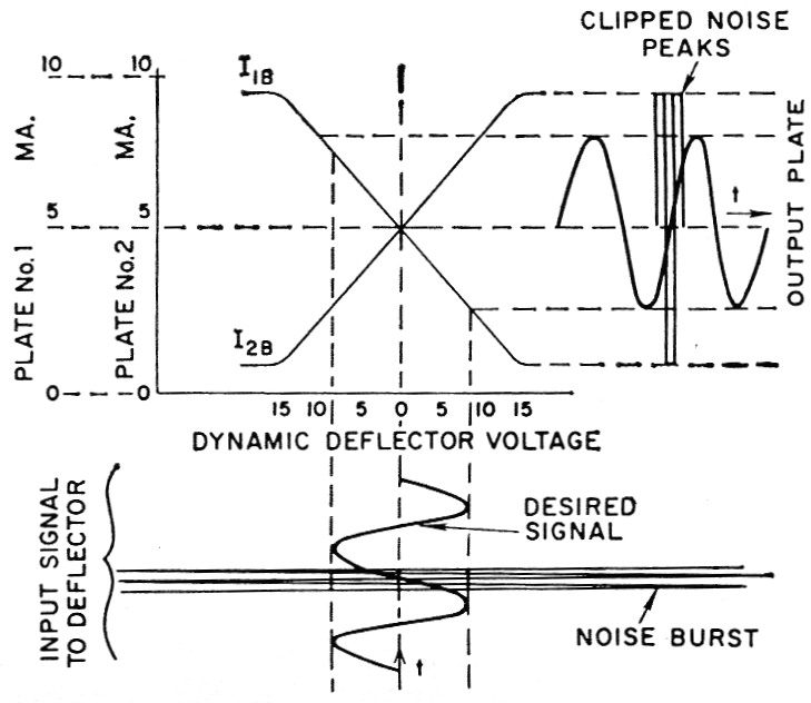
Fig. 6. Graph representing the signal-limiting properties of the 7360.
Precautions
The 7360, like other types of beam-deflection tubes, is affected by stray magnetic fields. Variations in magnetic fields cause corresponding vanations in plate currents, and upset the tube's exceptionally good balance. Therefore, a tube shield is recommended for most applications.
Judging from the past articles in and correspondence to QST, there seems to be a great deal of interest in "home-brew" receivers. I might add that the experience gained from any sort of project dealing with receivers is worth more than the money invested in it.
Notes
- M. Crosby, "Reception with product detectors, "QST, May, 1956.
- Vance, "S.S.B. exciter circuits using a new beam deflection tube," QST, March, 1960.
- Crosby, "The HBR-16 Communications Receiver," QST, October, 1959.
John M. Flipczak, K2BTM.