A parametric amplifier for 1296 Mc
Try this on your crystal set!
At 1296 Mc. few vacuum-tube r.f. amplifiers show much improvement over a crystal mixer, but this paramp will literally bring in signals you never knew were there. Seldom do we have the opportunity to describe a device which offers so much for so little. By using a surplus klystron pump oscillator and sections of X-band waveguide, cost and metal work are kept to a minimum. Since the design has been successfully duplicated by at least 25 California u.h.f. men, you can consider the construction and adjustment techniques well proven.
If you are interested in parametric amplifiers, or have some sort of 1296 Mc receiving capability, this article is for you. It describes an easy-to-build parametric amplifier for 1296 Mc that will provide at least 25 dB gain with a noise figure less than 2 dB. Two of these amplifiers are currently operational at the authors' respective stations.
While present-day theories of parametric amplifiers are heavily encrusted with mathematics, certain general rules are evolving for an intuitive understanding of what goes on. Previous articles.(1) have gone into the theory and are recommended reading. The amplifier to be described here uses a few little tricks to get around the points that generally reduce the enterprising ham to a frustrated madman. The following rules merit your careful attention:
1) A well-designed parametric amplifier should have mechanical as well as electrical stability and simplicity, ease of tune-up, and smooth control. An amplifier that does not have these characteristics may work, but it does not repro-sent a practical communications device.
2) The ultimate noise figure possible to achieve in a parametric amplifier is determined essentially by the ratio of the signal frequency to the idler frequency. Since the signal frequency plus the idler frequency is equal to the pump frequency in amplifiers of this type, the rule is then the higher the pump frequency, the better the noise figure. Good practice and practical considerations indicate that the choice of a pump frequency on the order of 6 to 10 times the signal frequency is desirable.
3) Best noise figure and amplifier stability occur in the amplifier when all tuning adjustments are in the direction of reducing pump power for a given gain value. A recommended "round-robin" tune-up procedure will be described. Since the pump power is an important tune-up indicator, a good method for attenuating pump power is essential. Simply coupling a grid-dip oscillator to the circuit is the way to madness.
From these general rules we see that in order to amplify at 1296 Mc we need a pump frequency of at least 7800 Mc. The 2K25 (723A/B) reflex klystron available on the surplus market can provide 10 milliwatts output at 10,000 Mc. In testing this klystron we found a mode which tunes nicely through 9200 Mc. Choosing 9200 Mc for the pump frequency then establishes that our idler frequency will be approximately 7900 Mc.
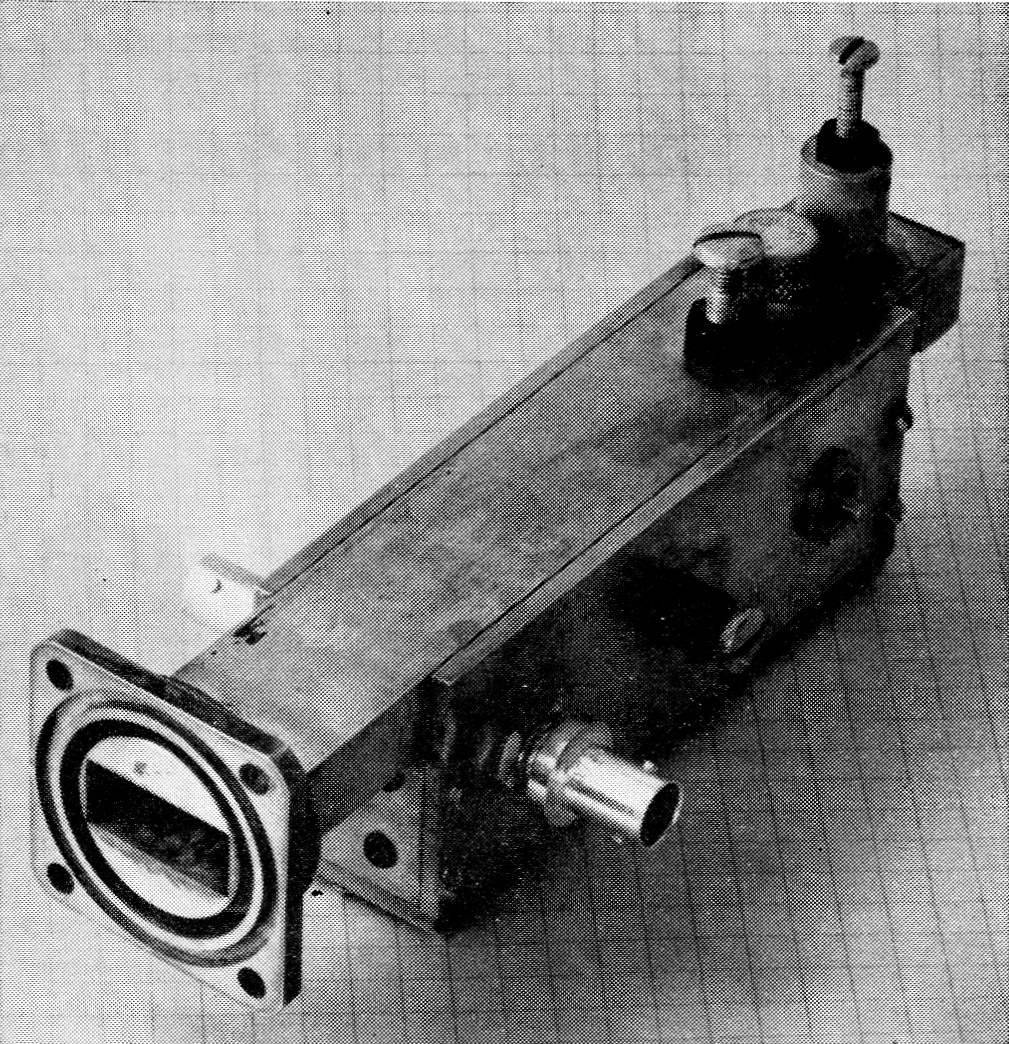
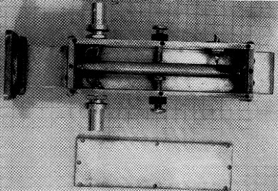
The choke flange at the left end of the amplifier connects to the pump unit, and the 9200 Mc pump signal enters the guide at this point. The screws on top tune pump and idler cavities which are formed by irises fitted into slots in the guide and a plate across the far end. Between the pump and idler tuning screws is the cap which holds the varactor crystal in its mounting. Below the guide section is the signal tank. The BNC fittings are for the input and output signals; which is used for which doesn't matter (until the amplifier is tuned up, that is!). The fine tuning screw is near the middle of the tank, and hidden on the other side is a screw for coarse tuning. Farther down the side of the tank is the feed-through capacitor at which bias is applied. Two of the four screws holding one end-plate bypass can be seen just below the waveguide.
The heart of the parametric amplifier is, of course, the diode. There are several diodes on the market which operate nicely on this amplifier. The authors recommend the Microwave Associates MAH-U diode(2) as the least expensive approach. Other good diodes (but expensive) are the MA 450C, D or E and the 460C, D or E. One of the new Sylvania diodes was tested and found to work very well. Other diodes such as the Hughes HPA series were tested but cannot be used in this amplifier design. They are self-resonant at approximately 1600 Mc, and require pump powers greatly exceeding the capability of the 2K25 klystron.
Pump and power supply
The klystron is mounted on a 10 cm length of standard X-band waveguide (1 × ½ inch outside dimensions) with one end closed and the other equipped with a flange for connection to the amplifier. This waveguide section is mounted on top of the 3 × 5 × 10 inch power-supply chassis near one end as shown in the photos. The klystron probe should project into the waveguide 1.1 cm. from the closed end. The probe has a metal jacket which covers all but about ¼ inch of its length. The end of this metal jacket should be just flush with the inside surface of the wave-guide. The jacket is above ground by the +B voltage, so cover it with insulating sleeving where it passes through the guide wall.
If you don't have a klystron socket, use an octal socket and drill out Pin 4 to accommodate the probe. Make a copper or brass cylinder ahich fits around the socket in order to mount it the proper distance above the waveguide. Heater and shell connections are made to the socket through holes in this cylinder. Be sure to provide some sort of shield around the klystron, as its outer shell is about 300 volt above ground. The pump power attenuator consists of a piece of resistance paper(3) which is inserted in a slot in the waveguide. The amount of insertion is adjusted with a small planetary dial. The slot is cut in the upper surface of the waveguide and runs lengthwise along the guide. It should begin 5 mm. back from the flange and be about 1 mm. wide by 35 mm. long. The resistance paper is shaped like the rotor plates of a straight-line frequency capacitor so that insertion area is nearly a linear function of rotation angle. Shape the paper so that 180 degree of rotation results in complete penetration. A flexible coupling between the dial and the 4 inch shaft will compensate for slight irregularities in the alignment of the supporting brackets. The resistance paper is cemented to a ¼ inch shaft coupling which facilitates assembly and adjustment.
The power supply diagrammed in Fig. 1 provides all necessary voltages for the klystron. One point of interest is the use of d.c. on the klystron filament. Klystrons at their best are noisy oscillators, and all this noise shows up when you attempt to obtain the maximum gain that is available from the parametric amplifier. We found that much of the noise was being coupled to the electron beam from the filament circuit, so 6 volts d.c. was obtained from four germanium diodes in a full-wave bridge operating from filament transformer T2.
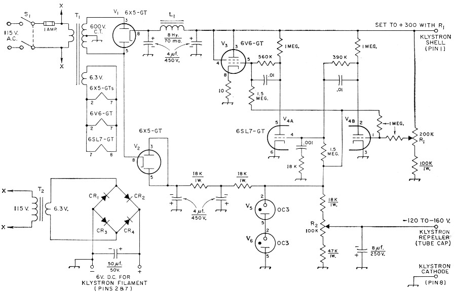
Fig. 1. Circuit of the power supply for the klystron pump. Capacitances are in µF; capacitors marked with polarity are electrolytic, others are paper. Resistances are in ohm, and resistors are ½ watt unless otherwise specified.
| CR1,CR2,CR3,CR4 | 150 mA, 100 p.i.v. germanium diode (G.E. 1N91). |
| L1 | Filter choke, 8 H, 70 mA (Stancor C1355 or similar). |
| R1 | 200 kΩ, 2 watt control, audio taper. |
| R2 | 100 kΩ, 3 or 5 watt, 10 turn control, linear taper (Borg Model 1111 B or 205 "Micropot"). |
| S1 | D.p.s.t. toggle. |
| T1 | Power transformer, 600 V. c.t., 70 mA; 6.3 V, 2 A or more (Thordarson 22R02 or similar). |
| T2 | Filament transformer, 6.3 V, 1 A (Thordarson 21 F08 or similar). |
The output voltage from T1 and full-wave rectifier V1 is electronically regulated by V3 and V4 and applied to the klystron shell. R1 sets this voltage to 300 volt, the desired value. Half-wave rectifier V2, working from half the secondary of T1, operates VR tubes V5 and V6 which provide a reference voltage for the electronically-regulated supply. R2 is connected as part of a voltage divider across the VR tubes and used to adjust the negative voltage on the klystron repeller. The 10-turn potentiometer specified for R2 is strongly recommended since its high resolution makes tuning up the amplifier much easier. However, if cost is very important, a standard 2-watt composition potentiometer can be substituted at the expense of more critical adjustment.
Construction of the power supply is not critical - just a little crowded with the chassis size specified. Power leads are brought out through the top of the chassis and terminate at a barrier strip for convenience.
Amplifier construction
The amplifier is made from 1/8 inch brass stock and X-band waveguide. Lighter brass stock can be used, but we do not recommend thicknesses less than 1/16 inch because of mechanical and thermal instability. Silver plating is not required for good operation, but if you have the facility, go ahead; it won't hurt a thing. Figs. 2, 3 and 4 show the construction details, and the photographs show the appearance when completed.
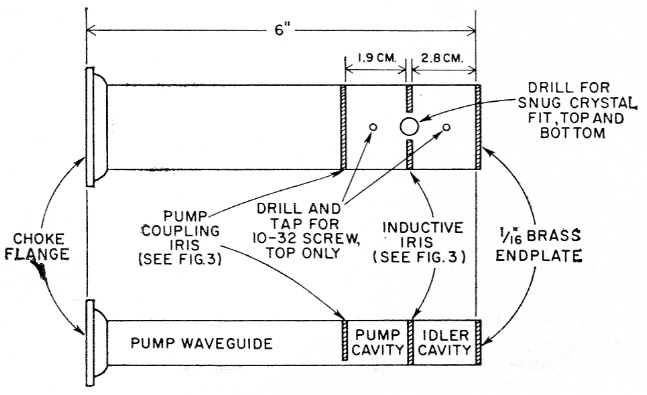
Fig. 2. Top and side views of the wave-guide section used in the amplifier assembly. Note how the guide is slotted from the top to accept the pump-coupling iris and from the sides to take the two halves of the inductive iris. The latter slots should end between 1/32 and 1 /16 inch from the crystal mounting holes. The holes for the tuning screws should be centered in their respective cavities. Cavity dimensions shown are for standard X-band waveguide (1 × ½ inch outside) and must be modified as explained in the text for guides of a different size.
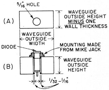
Fig. 3. (A) The iris used to couple pump energy into the pump cavity. The 5/16 inch hole is centered horizontally and off-center vertically by one wall thickness.
(B) Details of the crystal mounting and the inductive iris used to couple the crystal to the pump and idler cavities. Both irises are 1/32-inch brass.
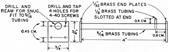
Fig. 4. Details of the signal-tank inner conductor and end-plate bypasses. This assembly should be mounted in the signal tank so that the center of the inner conductor is 0.8 cm. below the bottom surface of the waveguide section. The piece of /-inch brass tubing soldered into the inner conductor slips over the tip of the diode.
The waveguide section is 6 inches long and equipped with a choke flange at one end for connecting to the pump waveguide. A choke flange is one that has a ¼ wavelength groove cut around the rectangular opening in the face. The groove is to prevent r.f. leakage out of the joint when a flange-to-flange connection is made. Actually, only a very small leakage will be experienced at this power level, and two plain flanges will work nicely, but the choke type costs little more and was used for the sake of purity.
The 9200 Mc, pump energy is transferred from the transmission line part of the waveguide into the pump cavity by means of a resonant iris. The diameter of this iris is 5/16 inch and is quite important. If you choose a pump frequency other than 9200 Mc you will probably want to experiment with different size irises to minimize the v.s.w.r. between the pump generator and the pump cavity. Alternate methods of adjusting the line v.s.w.r. are all right, but the fewer knobs you have to adjust during alignment the better.
The pump cavity is made slightly less than a guide half-wavelength long at the pump frequency to allow tuning with the No. 10 screw plunger. If you use standard X-band waveguide, the pump and idler cavity dimensions shown are valid.(4) If you use other size guide, the guide wavelength can be found from the formula

where λg is the guide wavelength, λo is the free-space wavelength, and λc is the guide cutoff wavelength. The latter is equal to twice the longer inside transverse dimension of the waveguide for the TE1,0 mode used here. The same units should he used for all three wavelengths in this expression.
As an example, another available X-band waveguide measures 1¼ × 5/8 inch outside and has a 1/16 inch thick wall. The cutoff wavelength is therefore 2 × (1¼ - 1/8) = 2¼ inch, or 5.72 cm. The free-space wavelength corresponding to 9200 Mc is 30,000/9200 = 3.26 cm. From the formula above, λg = 3.97 cm, and the cavity lengths should be adjusted accordingly.
At the back of the pump cavity the parametric diode is centered in an inductive iris which couples the diode to both the pump and idler cavities. This iris should clear the crystal by at least 1/32 inch and not more than 1/16 inch. These dimensions represent rather loose coupling, which is desired. This contrasts sharply with other amplifiers which have been described and is probably the key to the ease of tune-up, stability and the very small amount of pump power required for proper operation. The loose coupling allows excellent Qs to be attained in all of the tuned circuits. Four different amplifiers have been built and tested with operating powers on the order of 8 dB below a 10-milliwatt level.
The crystal holder was made by drilling out the center of a microphone jack to a snug fit for the crystal cartridge. The jack must also be cut and filed down until only the flange and a couple of threads remain, so that the bottom end of the brass ferrule of the crystal comes just flush with the inside surface of the waveguide. This will provide the necessary clearance at the other end of the crystal where the tip goes through into the signal tank. The fitting is then soldered to the guide. A "cap" to hold the crystal in place can be made from a nut which will screw onto what's left of the mike connector. Solder a washer into the threads of the nut where it will bear on the end of the crystal when the nut is screwed in place. The rear end of a BNC screw-type chassis connector can be similarly manhandled to provide an alternative mounting.
Bottom view of the amplifier with the signal tank cover plate removed. The input and output connectors are near the left end, and the tuning screws are in the middle. The lower screw with the nut soldered to the end is used for coarse tuning, and the upper screw gives a fine adjustment. The 500-µµf. feed-through capacitor and the 1500-ohm Y-watt resistor for supplying bias to the diode are near the right end.
Particular care should be used when constructing both the resonant iris and the inductive iris to be sure that no burrs or filings are left in the cavities. After soldering and cleaning, run a sharp-tipped screwdriver or scribe point along the solder bead to verify that you have a clean metallic joint rather than a film of solder flux.
In back of the inductive iris is the idler cavity with its tuning screw. This screw is shown mounted on a machined r.f. choke which would be hard for most builders to duplicate. However, the simple screw and locking nut used for the other adjustments will work fine here, too. Do not solder the end plate on the idler cavity until you are satisfied that the iris and the crystal mounting are completely satisfactory. Hold the end plate tightly in place with tape until you have tested the amplifier; then solder it in place.
The signal-frequency tank is the part of the amplifier built from sheet stock and mounted below the waveguide section. The side pieces of the tank are soldered to the sides of the guide, and the bottom surface of the guide becomes the top of the tank. The tank ends and bottom plate are fastened to the side pieces with screws as shown.
The diode is coupled into the signal tank through a hole the diameter of the crystal body in the bottom of the waveguide. When properly positioned, the part of the brass tip which connects to the ceramic body of the crystal cartridge should just clear the bottom of the waveguide. This is critical since it is a part of the r.f. choke which prevents the pump energy from getting into the signal tank.
The tank inner conductor is made of 5/16 inch diameter brass tubing (available from hobby shops) and is mounted off-center to contain the field as far up in the tank as possible. This allows adjustments to be made with the bottom plate off. A ¾ inch square brass plate is soldered to each end of the tubing. These plates, separated from the ends of the tank by 0.01 inch Teflon or Mylar, form bypass capacitors and ground the inner conductor at each end for r.f. In the original amplifier, four 4-40 nylon screws were used to hold each bypass "sandwich" together. If such screws cannot be obtained, use metal ones with insulating washers where they pass through the end walls of the tank.
Since the line is insulated from ground for d.c., biasing voltage for the diode can be applied to one of the end plates. The resistor that feeds the bias to the line is a combination non-critical r.f. choke and an important diode protector in case you accidentally apply an improper amount of bias voltage.
The diode tip is connected to the inner conductor with a short piece of 1/8 inch diameter brass tubing. One end of this tubing is soldered into a hole drilled into the inner conductor, and the other end is slotted to fit snugly over the brass tip on the crystal.
The tuning screws for the signal tank are located at the center of the tank (r.f. voltage maximum point) and tune the tank capacitively. One screw has a nut soldered on the end and is used for coarse tuning. The other, left plain, provides a fine adjustment.
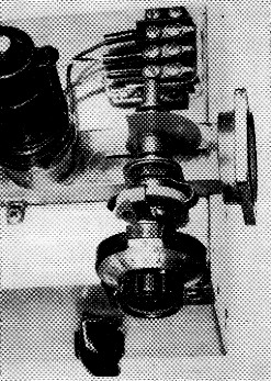
Close-up of the pump klystron and attenuator mounted on one end of the power-supply chassis. The flange connects to a similar one on the amplifier unit. The resistance paper vane, shown partially inserted in the waveguide slot, is supported between brackets in front and in back of the guide and is adjusted with the planetary dial (Lafayette F-348) fastened to the front of the chassis. The other knob is for setting the repeller voltage. Power connections are brought out to the barrier strip, and from there wires run through holes in the brass cylinder used to mount the klystron socket above the guide.
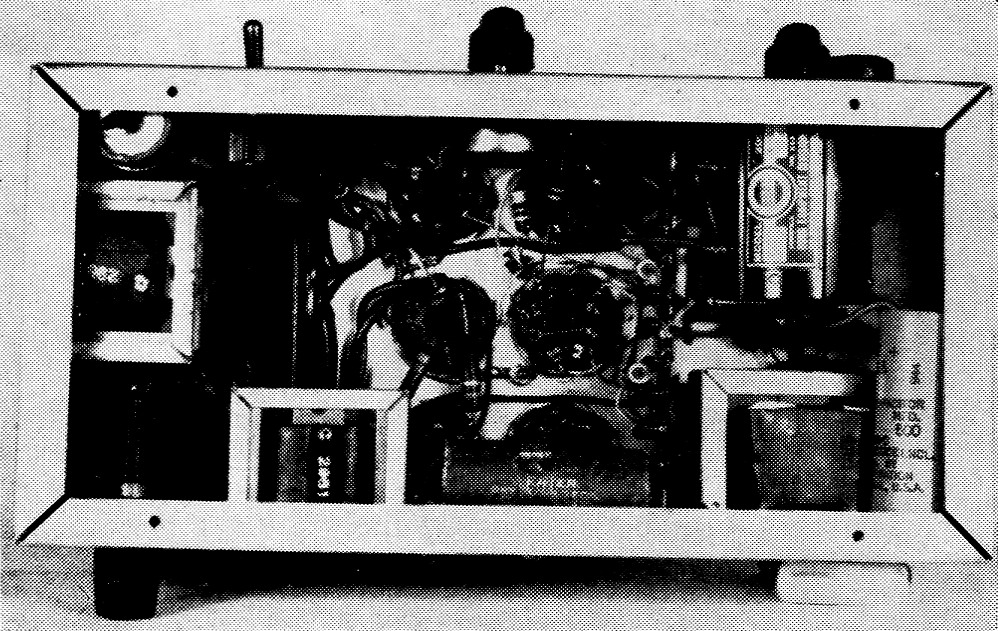
Bottom view of the pump and power-supply chassis. From left to right across the front panel (top) are the power switch, control R1for setting the klystron shell voltage and the 10 turn "Multipot," R2, for adjusting the repeller voltage. The fuse holder is on the rear panel. Parts placement is not critical, but the upper surface of the chassis at the right end must be left clear for the klystron and attenuator. In this version, the power transformer is at the left, and the six rectifier and regulator tubes are grouped in the middle. Chokes Li and L2 are mounted below chassis on the left end and on the rear apron next to the fuse. Filament transformer T2 appears in the lower right corner.
The input and output links are placed at the opposite end of the tank from the diode for symmetry. At these frequencies it is possible to excite various undesirable modes of operation, and lack of symmetry may suppress the very mode you want. The links are mounted on the BNC screw-type input and output fittings (Amphenol 31-102) and should be 1/16 to 3/32 inch from the inner conductor. The fittings screw into threaded holes in the sides of the tank 1 cm. from the inside surface of the end plate and allow adjustment of coupling during alignment. Then they can be secured for normal operation by tightening the mounting nuts. In general, you will find that the antenna coupling must be a little tighter than the output coupling. Don't be misled by appearances, though, as a slight difference in the positioning of the links can mean a vast difference in the degee of coupling.
Tune-up and operating procedure
First you must determine whether or not the klystron pump generator and the pump cavity are compatible. To do this install a test diode such as a 1N21 in the amplifier. Measure the rectified diode voltage with a v.t.v.m. connected to the bias feed-through capacitor. The pump cavity screw should tune well out of the cavity when you are close to 9200 Mc. with the klystron. The exact frequency used does not matter except that the difference between it and the signal frequency must be within the tuning range of the idler cavity. Adjust the pump cavity tuning and the klystron tuning (repeller voltage) for maximum diode voltage. This should be 5 volts or more, depending on the test diode used. The exact value is not important; all you are after here is to check the pump generator for output and the pump cavity for tuning.
Now replace the 1N21 with the parametric diode and repeat the tuning process. No external bias is used yet. You should note two things at this time: (1) The diode voltage is quite low, on the order of 0.3 to 0.7 volt. This is all right - you have a poor rectifier, but possibly a good voltage-tunable capacitor. (2) The pump cavity probably had to be retuned considerably because of the capacitive reactance of the diode.
Now with everything tuned up for maximum diode voltage, carefully tune the idler cavity through its range. At some point the voltage should kick up to between 0.9 and 2.0 volt. If it doesn't kick up, try another combination of pump frequency and pump cavity settings because it is likely that you are out of the range of the idler cavity tuning (assuming that the diode is not defective). Set the idler tuning at the kick point for now. Some diodes have a sharp kick, while others have a generally broad rise in voltage as the idler is tuned. Either indicates that the signal circuit is oscillating, and if it is not operating at an undesirable mode it should be oscillating around 1300 Mc. At this point you should be able to connect your present 1296 Mc crystal set to the paramp and hear the oscillation as a loud, rasping buzz.
A signal source, preferably tone-modulated, is needed for the next step. If you don't have one, simply follow standard operating procedure for the 1296-Mc. band and telephone one of your friends for an appointment to turn on his transmitter for you.
Connect the antenna or signal source to the paramp input and your present equipment to the output. Apply bias to the diode, using a reverse-bias voltage of approximately 0.7 volt. The bias supply can be a 10,000-ohm 10-turn potentiometer (similar to R2) connected as a voltage divider across a 1.5 volt battery. Again a regular composition potentiometer can be substituted if necessary. With no pump power applied (maximum attenuation) adjust the signal tank coarse-tuning screw for maximum signal in the receiver. Now increase pump power to maximum and carefully tune the idler cavity until you hear oscillations in your receiver. Reduce pump power until oscillations just stop, and then retune the idler cavity for oscillation again. At this point you must start a systematic round-robin procedure or you will get lost. Refer to Rule 3 near the beginning of the article and proceed as follows:
(All adjustments are for either oscillation or for a given value of signal gain with reduced pump power.)
| Retune idler | reduce pump power |
| Adjust bias toward zero | reduce pump power |
| Adjust repeller voltage | reduce pump power |
| Retune signal tank (fine tuning screw) | reduce pump power |
| Adjust input and output links | reduce pump power |
| Retune pump cavity | reduce pump power |
At some point in these proceedings you may find that the gain is still rising and that you have reached zero bias voltage. Simply reverse your bias polarity and continue the round robin, slowly increasing the bias voltage in the forward direction. The value of bias voltage that you end up with is a function of many things; you just have to find it for the diode you are using and the amplifier you have built. Typical values for approximately 15 diodes tested ranged from 0.3-volt forward bias to 0.7-volt reverse bias.
When you have reached the point where no further adjustments cause a gain in signal or a reduction of pump power for a reference signal, you are done. Now the pump power attenuator is your gain control. You should notice that an increase in pump power produces an increase in signal gain. A further increase in pump power will result in a small drop off in gain, and then as the power is further increased, the amplifier will break into oscillation. This gain reversal is quite convenient, as it allows a nice broad operating point and permits stable operation with minor variations in klystron pump power. Minor adjustment of the diode bias may be needed for maximum amplifier gain as the pump power is increased.
Once tuned up, this amplifier will remain stable over long periods of time without any adjustment other than the repeller plate voltage. Next time you set up the unit it will only be necessary to adjust the bias to the correct voltage, ride herd on the repeller voltage, and adjust pump power to the desired value.
This amplifier will provide a dramatic experience the first time you put it ahead of your crystal-mixer converter. With 25 dB plus of stable gain, the noise figure of your receiving setup is that of the parametric amplifier. Our units are currently providing a 5 S-unit gain on 75A-2 and 75A-4 receivers. If that looks like nearly 30 dB of gain, you are correct. Local Bay Area tests by K6UGH with W60110 and K6ONM have been very gratifying. Combined with a little transmitter power and a high-gain steerable antenna, this little gem should be just the thing for moon bounce.
Notes
- Bateman and Bain, "New thresholds in V.H.F. and U.H.F. reception," QST, January, February and March, 1959.
- Available to hams only for $10.00 from Microwave Associates, Burlington, Mass. Be sure to specify the MAH-U along with your amateur call.
- Suitable paper is commercially available but hard to locate. Old or surplus attenuators are one source. Ramage & Miller, Inc., 3221 Florida Ave., Richmond, Calif., will sell to hams an X-band attenuator which uses nonstandard waveguide for $4.00. This attenuator will provide two carbon-deposited vanes or might be used directly with some hard work in changing from one waveguide size to another. We have also had some luck in rubbing a soft lead pencil on a piece of paper and then coating the deposit with Krylon. This works all right since accurate calibration of the attenuation is not required. The problem is getting the graphite on heavy enough and holding it on so that the attenuation value doesn't change.
- Standard 1 × ½ inch guide has a cutoff wavelength of 4.57 cm. and a guide wavelength of 4.65 cm at 9200 Mc.
W.O. Troetschel, K6UQH, ex-W7LVO
H.J. Heuer, KH6CYI.