A 4-400A amplifier for c.w., s.s.b. or a.m.
Something different in high-power tank circuits.
How long since you've seen a kilowatt pi network that didn't use a commercial rotary or switched coil assembly and maybe a costly vacuum variable capacitor besides? This rig's plate circuit combines a novel home-brew switching system, two air variables and a store-bought coil set into a tank that's economical as well as efficient. Bias and screen supplies, plus control and metering circuits, are all included. All you have to furnish are the h.v. and a few watts (or volts on s.s.b.) of drive.
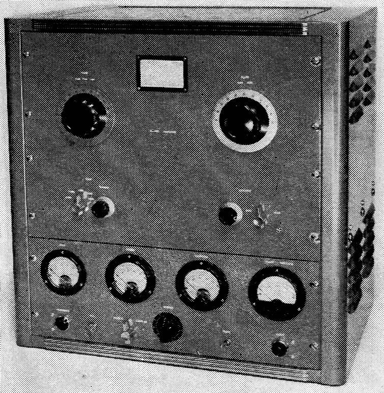
Here the 4-400A amplifier and its control unit are mounted in a 21-inch gray hammertone rack cabinet (Bud CR1727). Shelf brackets (Bud SA-1350) are mounted on both sides of the cabinet to hold the amplifier chassis. The meters are for grid, screen and cathode currents and plate voltage. Below them, from left to right, are the filament pilot light, key-type a.c. switch, Class AB1/C bias switch, screen autotransformer, plate switch and plate pilot light.
Have you been looking for a kilowatt final that doesn't take 100 watt of drive? So many amplifiers today are of the grounded-grid type and require large exciters. Any transmitter delivering about six watts will drive the amplifier described here to rated output on all h.f. bands. When used as a linear for side-band, a peak driving voltage of about 150 is required, and a 10B, 20A or similar exciter will provide adequate drive.
The amplifier can be run at a kW input on c.w., 880 watt input on a.m., and about a kW input p.e.p. as a Class AB1 linear. (Maximum input with a two-tone test signal is 650 watt.)
The plate tank circuit of the amplifier is made from readily available parts. No expensive plate inductor or vacuum variable capacitor are required. The amplifier is fairly economical to build and operates with excellent efficiency. Bias and screen supplies plus all the necessary control circuits are included.
4-400A amplifier
Checking Fig. 1, it can be seen that the amplifier uses the conventional grounded-cathode, tuned-grid configuration. The grid tank consists of a link-coupled, parallel-tuned circuit, switch-able from 80 through 10 meter. S1B shorts out the unused part of grid coil L2, and S1A modifies the input link, L1. C1 peaks the input circuit within each band. A Harrington Electronics subassembly was used in the original rig, but an equivalent circuit can be built from standard parts if desired.
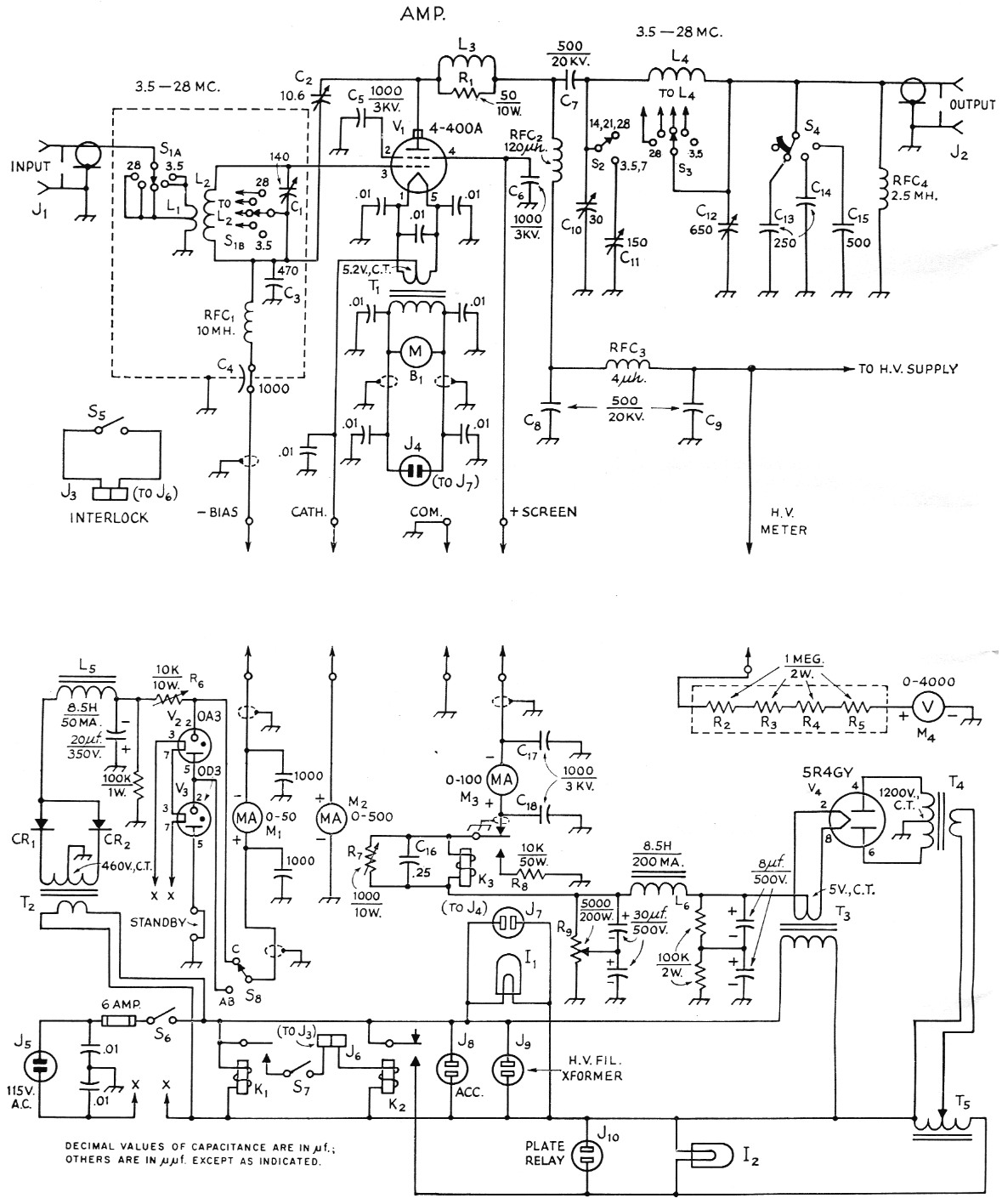
Fig. 1. Circuit of the amplifier (upper part of the diagram) and power supply/control unit. The grid circuit, C1L1L2S1, can be made up from the parts specified, or a Harrington Electronics GP-20L can be used. Interlock switch connectors J6 and J3 are connected by a length of line cord with a Cinch-Jones P-202-CCT plug on one end and an Amphenol 61 F1 1 socket on the other. Millen 37001 safety terminals are used for the h.v. connections. Resistances are in ohms, and resistors are ½ watt unless otherwise specified. Capacitors not listed on the facing page are 600 volt disk ceramic except those marked with polarity which are electrolytic.
| B1 | Blower-motor assembly, 17 c.f.m. (Ripley, Inc., Middletown, Conn., type 8433). |
| C1 | 140 pF midget variable (Hammarlund APC140-B). |
| C2 | 10.6 pF neutralizing (Johnson N250). |
| C3 | 470 pF 500 volt mica. |
| C4 | 1 nF feed-through (Centralab FT-1000). |
| C5,C6,C17,C18 | 1 nF, 3000 volt disk ceramic (Centralab DD30-102). |
| C7,C8,C9 | 500 pF, 20 kV ceramic (Centralab TV-207). |
| C10 | 30 pF variable, 0.25 inch spacing (Barker & Williamson CX-30C butterfly, one section used). |
| C11 | 150 pF variable, 0.25 inch spacing (Johnson 150D90). |
| C12 | 650 pF variable (two Hammarlund MC-325Ms ganged and paralleled). |
| C13,C14,C15 | 2500 volt mica (Aerovox 1652L). |
| C16 | 200 volt molded paper. |
| CR1,CR2 | 500 mA 600 volt peak inverse silicon diode (Sarkes Tarzian F-6). |
| I1,I2 | 115 volt pilot lamp. |
| J1,J2 | Coaxial receptacle, chassis mounting (SO-239). |
| J3,J4,J5 | 115 volt plug, chassis mounting (Amphenol 61-M1). |
| J6 | 2 contact socket (Cinch-Jones S-202-B). |
| J7-J10, inc. | 115 volt socket (Amphenol 61-F1). |
| K1 | S.p.s.t., 115 volt 60 second time-delay relay, normally open (Amperite 115N060). |
| K2 | S.p.d.t. relay, 115 volt a.c. coil (Potter & Brumfield KA5AY). |
| K3 | S.p.d.t. relay, 2500 ohm 7.2 mA coil (Advance GHE/1C/2500). |
| L1 | 3¾ turns No. 18 insulated wire on cold end of L2; tapped 2 turns from ground end. |
| L2 | 50 turns No. 24 tinned, 1¾ inch long on ¾ inch diam. ceramic form; tapped 5, 8, 13 and 25 turns from grid end. |
| L3 | 3 turns No. 10 tinned, 5/8 inch diam., 1 inch long. |
| L4 | Pi-network coil assembly (Air Dux 195-2 available from Illumitronics Engineering, Sunnyvale, Calif.); see text. |
| L5 | 8.5 H 50 mA filter choke (Knight 62G136). |
| L6 | 8.5 H 200 mA filter choke (Knight 61G409). |
| M1,M2,M3 | D.c. milliammeter. |
| M4 | D.c. voltmeter; includes R2-R5, inc. (milliammeter can be substituted; see text). |
| R1 | 50 ohm 10 watt noninductive wire-wound (Sprague l0NIT). |
| R2-R5, inc. | Part of M4 if voltmeter is used. |
| R6,R7 | 10 watt adjustable. |
| R8 | See text. |
| R9 | 200 watt adjustable; set tap at midpoint. |
| RFC1 | 10 mH r.f. choke (National R-50-I). |
| RFC2 | l20 µH plate r.f. choke (Raypar RL-101). |
| RFC3 | 4 µH r.f. choke (National R-60). |
| RFC4 | 2.5 mH r.f. choke (National R-50). |
| S1 | Miniature ceramic rotary, 2 poles, 6 positions, 1 section, shorting, 5 positions used (Centralab PA-2002). |
| S2,S3 | Homemade, see text and Fig. 2. |
| S4 | Ceramic rotary, 9 positions, 1 section, progressively shorting, 4 positions used (Centralab PISD section and P-270 index assembly). |
| S5 | S.p.s.t. snap-action (Unimax 2HBW-1). |
| S6 | S.p.s.t. lock switch (Arrow-Hart & Hegeman 81715-L). |
| S7 | S.p.s.t. toggle. |
| S8 | Ceramic rotary, 1 pole, 6 positions, 1 section, nonshorting, 2 positions used (Centralab 2501). |
| T1 | Filament transformer, 5.2 volt c.t., 24 A (Triad F-11U). |
| T2 | Power transformer, 460 volt c.t., 50 mA (Stancor PC-8418). |
| T3 | Filament transformer, 5 volt c.t., 3 A (Thordarson 21 F03). |
| T4 | Power transformer, 1200 volt c.t., 200 mA (Thordarson 22R36). |
| T5 | Variable autotransformer, 0-132 volt, 1.75 A (Superior 10B). |
The amplifier is neutralized by the capacitive bridge system with neutralizing capacitor C2 connected from the plate of the amplifier tube to the bottom of the grid circuit. C2 and C3 form a capacitive voltage divider, and their ratio determines the amplitude of the feedback voltage used in neutralizing. C2 must have adequate insulation to withstand full peak plate voltage.
The amplifier output circuit is a shunt-fed pi network capable of working efficiently into 50- or 70-ohm loads on all bands from 3.5 through 30 Mc. A choice of two different tuning capacitors is available; the smaller capacitor, C10, is used on 20, 15 and 10 meters, and the larger one, Cn, is paralleled with it for tuning 80 and 40 meters. Having two plate-tuning capacitors allows a desirable L/C ratio to be maintained at all frequencies without having to resort to a vacuum variable.
The output side of the pi network has a 650 pF variable loading capacitor (two 325-µµf. variables ganged) and three additional fixed micas which can be paralleled to give an additional 1000 pF. The r.f. "safety" choke shunted across the output is to short the plate voltage to ground in the event blocking capacitor C7 should fail. This insures against d.c. appearing on the pi network or feed line.
A 17 c.f.m. blower supplies adequate forced air cooling to the 4-400A base and plate seals. The blower is connected across the 4-400A filament transformer primary and operates whenever the filament is energized.
Control circuitry
Included with the amplifier but mounted on a separate chassis are all required control and metering circuits. Meters are provided for amplifier grid current, screen current, cathode current and plate voltage. To comply with the FCC rule regarding measurement of input powers over 900 watt (section 12.131 ), the control grid and screen currents should be subtracted from the total cathode current, and the result is multiplied by the plate voltage to determine the plate power input.
The amplifier is fixed biased at -225 volt for Class C and -150 volt for Class AB1 operation. VR tubes hold the bias voltage constant. The full-wave rectifiers in the bias supply are silicon diodes, so there is no warmup time involved and full operating bias is applied to the amplifier when the power switch, S6, is closed. Time-delay relay K1 operates K2, which is in series with the screen supply primary. Thus there is a 60 second delay before screen potential can be applied to the amplifier tube. The screen supply rectifier (V4) filament is not controlled by the time-delay circuit.
Likewise, the accessory a.c. socket, J8, and the high-voltage filament transformer socket, J9, are energized as soon as power switch S1 is closed. The h.v. plate transformer is turned on by a relay plugged into J10 and controlled by the time-delay relay. With this arrangement, it is impossible to apply a.c. to the plates of the high-voltage rectifiers before the filaments have had a chance to warm up.
A variable autotransformer in series with the screen-supply primary allows the screen voltage to be adjusted from zero to about 800 volts under load. This makes a convenient arrangement not only for resetting the screen voltage when changing from Class C to Class ABI or vice versa, but also for adjusting the power input of the amplifier.
A screen overload protection circuit is also included. If excessive screen current flows, K3 is energized and is kept energized by the current through R8.(1) To reset the relay the screen voltage must be momentarily turned off so that the relay will return to its unenergized condition.
This view of the amplifier shows the band-switch trap door, air-exhaust port and hole (center, left) for adjusting neutralization, all in the top of the shielding enclosure. The large knob on the left of the panel is for the 20/15/10 meter plate tuning capacitor, and the matching knob adjusts the capacitor used on 80 and 40. Farther down, from left to right, are the grid band switch, grid tuning control, variable loading adjustment and loading switch.
This can be done by opening t.r. switch S7. The current at which the overload relay throws is set with shunt resistor R7.
The plate voltmeter can.be purchased as such or made from a milliammeter. The voltmeter circuit shown in Fig. 1 consists of a 0-1-ma. meter in series with four 1-megohm resistors. The meter resistance is very loss in comparison to megohms, so with 4000 volt across the series combination, the current will be very nearly 1 mA, and the meter will read full scale. The meter reading can be multiplied by a conversion factor (4000), or the meter face can be recalibrated to read 0-4000 volt.
Amplifier construction
The amplifier is built on a 4 × 13 × 17 inch chassis and uses a 14 inch rack panel. All major components are visible in the photographs. The Harrington grid circuit, output loading capacitors and switch, and filament transformer are all below the chassis. Mounting the filament transformer in the center helps keep the weight evenly distributed.
Because the rotor of grid capacitor C1 can be as much as 225 volt negative in respect to the chassis, an insulated coupling must be used between the rotor and the shaft going to the grid tuning knob. Leads from the grid circuit are brought out through a 3 × 5 inch aluminum back plate via a feed-through capacitor and bushings. The input link is connected to the coax receptacle through a length of RG-58/U. The flanged cover of a 5 × 4 × 3 inch Minibox is slipped over the grid assembly, and this cover is secured to the back plate with four self-tapping screws and to the main chassis with four 6-32 spade bolts. This enclosure provides adequate shielding for the grid circuit and minimizes r.f. feedback which would cause instability.
The ganged loading capacitors (C12) are mounted off the chassis on 1-inch metal spacers. Connections in the output circuit are made with copper or brass strapping to provide low-inductance leads.
The 4-400A tube socket is held by four tabs that are evenly spaced around a 3¾ inch diameter circular cutout as shown in the bottom view. This arrangement allows maximum air flow around the 4-400A glass bulb. An Eimac chimney (SK-406) channels the air around the tube and up toward the plate seal. A cork gasket between the chassis and the chimney provides a tight seal with minimum air leakage. The four-inch square of cork stock used in making the gasket should be obtainable from most automotive supply stores where it is sold for gaskets, or from a floor-covering supply store which carries cork tile. A 3 inch diameter hole covered with perforated sheet aluminum ("do-it-yourself" type) is located directly above the 4-400A tube. in the shielding enclosure. This hole allows the cooling air to escape from the enclosure.
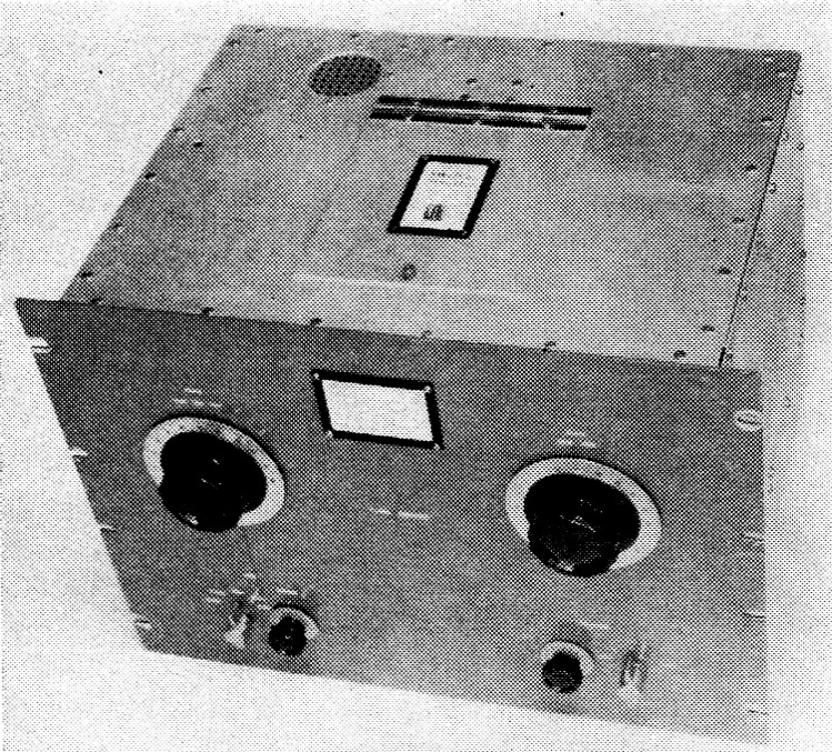
The control unit. On the chassis, counterclockwise from the upper left, are the screen overload relay, cage containing voltmeter multiplier resistors, screen power transformer, filament transformer for the 5R4 screen rectifier, 5R4, screen filter choke, bias transformer, bias VR tubes, bias supply choke, time-delay relay and jack for the leads from the interlock switch. On the rear of the chassis, from left to right, are a terminal strip for ground, screen and grid connections, a.c. input plug, fuse holder, a.c. output for the h.v. rectifier filament transformer, a.c. socket for the amplifier filament transformer, accessory a.c. socket, a.c. socket for the h.v. control relay and standby terminals. The free terminal on the second meter from the left connects to the amplifier cathode.
The blower is mounted on the rear apron of the chassis by four 6-32 spade lugs attached to the walls of the blower output housing. A 1¼ × 1_1/8 inch hole must be cut in the rear apron of the chassis to accommodate the blower, and another cork gasket is used here between the plastic blower housing and the amplifier chassis.
The chassis should be as airtight as possible to provide maximum air flow to the 4-400A tube. This requires sealing any small holes such as exist in the corners of the chassis. These holes can be covered with tape or filled with Duco cement. The bottom plate must, of course, be solid (not perforated) aluminum for the same reason.
Plate tank and enclosure
The plate tank coil, L4, band switch, S3, and plate tuning capacitor switch, 52, are mounted on two Lucite plates in the center of the chassis. The tank coil comes prewound on one Lucite plate which is positioned 3½ inch above the chassis on ceramic spacers. Mounted 3½ inch above this, again on ceramic spacers, is the 4_1/8 × 8 inch Lucite band-switch plate detailed in Fig. 2. When drilling this plate be sure to use a slow speed; otherwise, the Lucite will soften and produce irregular holes. Hard rubber washers (the type used for packing faucets) are inserted between the ceramic spacers and the Lucite plates to provide a tight fit.
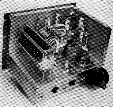
Most of the enclosure has been removed here to show the low-and high-frequency plate capacitors (left and right), the coil and band-switch assembly (center) and the 4-400A in its glass chimney. The neutralizing capacitor is behind the tube in this view. The cork gasket can be seen between chimney and chassis. Across the rear apron are the output jack, filament a.c. plug, cathode and ground terminals, high-voltage connector, ground post and blower; the latter hides another barrier strip (for bias and screen connections) and the input jack.
The actual band switch is made from a 3¼ inch aluminum utility handle (Bud UH-71A), two jumbo banana plugs (Johnson 108-770) and six banana jacks (Johnson 108-760). The capacitor switch is of similar construction, using one utility handle, two banana plugs, and three banana jacks. In order to strengthen the soft aluminum utility handles used for the switches, cross supports are run from one end of each handle to the other.
Counting from the blocking capacitor end, the plate coil is tapped at 4 turns (0.4 µH) for 10 meter; 7.5 turns (1 µH) for 15 meter; 10.5 turns (2.33 µH) for 20 meter, 14 turns (5.2 µH) for 40 meter, and 24 turns (16.4 µH) for 80 meter. (All the figures include the 4-turn coil made of 3/8 inch strap.) The lugs provided with the tank coil assembly should be securely soldered to the coil at these points. Strapping should then be run from these taps to the appropriate band-switch terminals. It should be noted (Fig. 2) that the band-switch terminals do not progress in consecutive order, but rather are arranged to provide the shortest possible lead lengths.
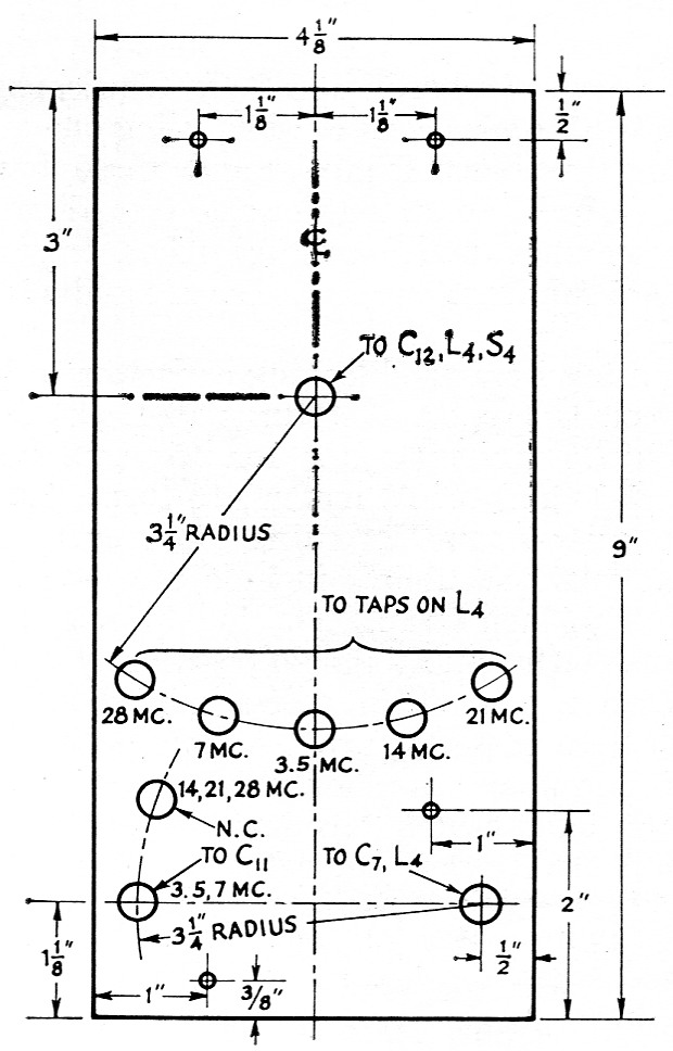
Fig. 2. Layout of the ¼ inch Lucite or Plexiglas plate used to mount the band switch and capacitor switch. Suitable material can be obtained from most plastic supply stores. The large holes are %-inch diameter, and the small ones are drilled to pass 6-32 screws. Holes for stator jacks (marked with frequencies) are spaced 7/8 inch apart along their respective arcs.
One end of the blocking capacitor, C7, is threaded onto the stud that anchors the free end of the 4 turn 10 meter tank coil, and the other end of C7 is connected to the plate r.f. choke with strapping. The output end of the tank coil assembly is connected via a feed-through bushing and more strapping to the variable loading capacitor.
One precaution - be sure no iron or steel hardware is used in the band-switch assembly, or for that matter, anywhere in the plate tank circuitry of the amplifier. Each piece of hardware should be checked first with a magnet to insure that it is neither iron nor steel before being used in the plate circuit.
The shielding enclosure is made from aluminum sheet and angle stock. The two side pieces measure 10 by 13 inch, the top 13 by 17, and the back 10 by 17. The back, top and sides of the enclosure are fastened together with lengths of the angle stock (Reynolds Item 6A) drilled and tapped for 6-32 screws. The enclosure is also secured to the chassis and front panel hacking plate by 6-32 screws. This arrangement makes a tight enclosure with minimum leakage.
The mounting feet of butterfly capacitor C10 are screwed to the side of the enclosure. Long screws and spacers (like the ones used to mount C11) connect the front plate of C10 with the panel.
In order to get to the band switch and capacitor switch, a trap door is provided in the top of the enclosure. Snap-action switch S5 is installed so that it is actuated by the trap door. The four screws holding the microswitch can be seen directly behind the trap-door hinge. The leads from S5 are brought out to a jack, J3, located on the back wall of the enclosure. A plug-in cable connects J3 and J6 on the control unit. Lifting the trap door makes it impossible for the screen or plate supplies to be energized. The trap door measures 6¼ by 7 inch and the rectangular cutout in the top of the enclosure is 4_3/8 by 6¼ inch. This provides adequate overlap to prevent any leakage of r.f.
The control unit
Construction of the switching/metering/power unit is pretty much conventional. The front panel is spaced 2½ inch out from the chassis to provide room for mounting the auto-transformer and plate and filament pilot-light assemblies. For the most part, component placement is noncritical. Screen-supply bleeder R9 gets rather hot and should be isolated from other components. Ventilation holes are drilled in the chassis above R9 and also above screen overload resistor R8 to help provide cooling. Multiplier resistors R2, R3, R4 and R6 are mounted on a phenolic board and enclosed in a metal cage as a safety precaution. The voltmeter input connector is mounted on top of the cage.
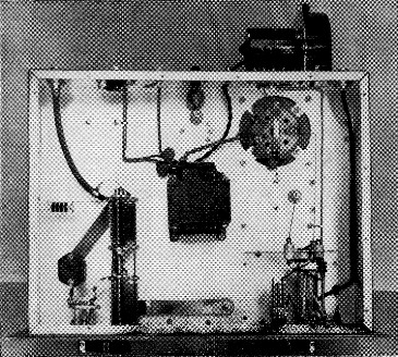
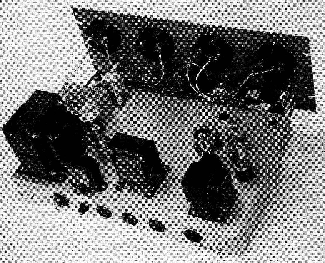
Bottom view of the amplifier. At the lower right is the Harrington grid circuit with the Minibox shield cover removed, and to the left are the loading capacitors, switch and "safety" choke. The filament transformer is in the center. At the upper right is the amplifier tube socket mounted on four tabs spaced evenly around the cutout in the chassis.
Adjustment and operation
First, determine that the control unit is operating correctly. Apply 115 volt to J5, insert the tubes, and turn on the key switch, S6. The green filament pilot light, I1, should go on immediately. There should also be power at receptacles J7, J8 and J9. J7 and J9 are for the amplifier and plate supply filament transformers; J8, an accessory socket, is provided so that external equipment such as the station receiver can be controlled by S6. There should be no power at J10, the plate transformer control socket.
Next, adjust R6 until the VR tubes just begin to glow. Be sure the standby terminal jumper from Pin 5 of V3 to ground is in place. Operating S8 should change the bias from -150 volt in the Class AB1 position to -225 volt for Class C in the other. With S8 in the linear position, and a voltmeter on the output of the bias supply, temporarily lift the standby jumper from ground. The output voltage should rise from -150 to approximately -300 volt. The standby terminals provide a convenient way to bias the 4-400A beyond cutoff during standby and receiving periods. This will prevent any annoying diode noise generation.
Open S6 and connect an a.c. voltmeter to J10. Put a temporary jumper between the two contacts of J6. Close S6 and S7, and after 60 seconds there should be power at J10 and the red plate pilot lamp should light. Replace the jumper across J6 with the leads from the interlock switch. Lifting the trap door should de-energize J10, and the plate pilot bulb, I2, should extinguish.
Next, connect a d.c. voltmeter to the output of the screen supply. By adjusting T5 it should be possible to vary the output from 0 to approximately 850 volt. Finally, adjust R7 so that K3 trips when 40 mA is drawn from the screen supply. This can be checked by connecting a resistor (620 ohm or less at 1 watt) across C17 and running the voltage up from zero until the drain is 40 mA. This completes the testing of the control unit.
The amplifier must now be neutralized. Set the grid and plate band switches for 28 Mc, and disconnect the screen and plate leads at the amplifier terminals. Couple a sensitive indicating wavemeter to the output end of the plate tank circuit and apply the required -225 volts of bias. Apply drive, resonate the grid circuit and adjust the output of the exciter for rated 4-400A Class C grid current. Neutralizing capacitor C2 should then be adjusted for minimum r.f. in the plate tank circuit. The plate tuning capacitor should be retuned for maximum wavemeter reading after each change of C2. After rated plate and screen voltages have been applied and the amplifier loaded, the neutralizing capacitor should be touched up so that minimum plate current and maximum grid and screen currents occur simultaneously as the plate tank is tuned through resonance.
Notes
If the amplifier is to be used for s.s.b., the h.v. power supply should have a minimum output capacitance of 8 µF. For best voltage regulation, the plate transformer should have a 220 volt primary. The output of the h.v. power supply should include a 500 mA fuse to protect the supply from excessive overloads.
If the amplifier is to be plate modulated, a choke, approximately 10 H at 50 or 100 mA, should be inserted in series with the screen lead of the 4-400A. An external switch can be used to short out the choke when using the amplifier for c.w. or s.s.b.
The high voltage lead from the plate supply can be made from RG-8/U, which is readily obtainable and has a 4000 volt d.c. rating.
Even though the transmitter is adequately shielded to prevent direct harmonic radiation, it is a good idea to use a low-pass filter to minimize the harmonics getting out via the transmission line.
- A somewhat more foolproof protection scheme was described by W9HRH in QST for October, 1960. - Ed.
Kenneth C. Lamson, W1ZIF.