Timing adjustments in a sequenced change-over system
A method of checking relay operation.
In an earlier QST article, the author pointed out the importance of operating change-over relays in proper sequence to avoid unnecessary noise in the receiver and arcing at the antenne-relay contacts. If one is to arrive at the minimum delay intervals required for fast VOX operation, some method of checking the timing is an invaluable aid. The latter is the subject of this article.
A previous article by the author(1) included some discussion of the contact performance of relays. Graphs were presented which illustrated the influence of contact bounce on the time which must be allowed for the contact to establish a solid connection. It was pointed out that failure to make due allowance for bounce may be responsible for arcing at the antenna relay contacts if transmitter power is applied before firm contact is set up at the antenna relay. Also, unnecessary pops and clicks may be introduced in the receiver if the receiver is not silenced before other change-over operations take place.
It seems obvious that these problems may be overcome simply by operating the relays in proper sequence and making the delay interval between the operation of one relay and the next sufficiently long to assure that one operation is complete before the next one is started. However, if one wants a VOX-operated change-over system that does not clip the initiating speech, the delay time must be cut to the minimum required for proper sequencing. The adjustment of timing then becomes a matter of accuracy that cannot be attained without the employment of some method of checking having a capability beyond that of any of the five senses.
In making the timing graphs that were a part of the previous article, a Tektronix 535 scope was used. This scope has a long-persistence screen and a sweep whose speed is accurately calibrated. With this scope and a few resistors, a good check of the relays in the adapter was obtained.
However, the number of amateurs who have Tektronix 535s at their disposal must be quite low. So it was decided to see what could be done with an instrument which is more common in amateur stations - the v.t.v.m. Using the test circuit to be described, the period of time between the closure of a relay contact, after bounce has stopped, and the time when the next relay starts to operate can be measured. This is the critical period to be checked to make sure that proper sequencing is obtained.
Test circuit
Fig. 1 shows the test circuit connected to the relays in the unenergized, or listening, condition. The test circuit, as shown, is connected so as to measure the period of time between the complete and solid transfer of the receiver-relay contact (X1 of K1) and the start of the antenna-relay contact (Y1 of K2) movement. The period to be measured corresponds to the time between the instant that contact X1 arrives at the X3 contact and stops bouncing, and the instant that contact Y1 leaves contact Y2.
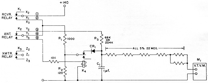
Fig. 1. Circuit used in testing relay sequencing. Resistances are in ohm, and resistors ½ watt unless indicated otherwise below.
| C1 | 1 µF 200 volt paper, 10 per cent. |
| CR1 | Silicon diode: 360 p.i.v., 200 mA (Sarkes-Tarzion K-200). |
| K1,K2,K3 | Relays under test (see Footnote 1). |
| K4 | S.p.d.t. 6000 ohm coil (Sigma 11F-6000G/SIL). |
| M1 | Conventional v.t.v.m., 11 MΩ input. |
| R1 | 20 W. |
| R2 | 2 W. |
| R3 | 5 % (see text). |
A time measurement occurs as follows: When contact X1 reaches X3, 140 volt through contacts Y1, Y2 and the timing resistor R3 starts to charge C1, the timing capacitor. C1 will charge until K2 operates and Y1 breaks contact with Y2. The voltage which appears across C1 during this period is a function of the period of time which we want to measure. The period of time which this voltage represents can be calculated, since the charging voltage of 140 volt, the value of R3, and the value of C1 are all known.
Eliminating effects of bounce
The unfortunate fact that X1 bounces when it makes contact with X3 complicates an otherwise simple measurement. The period of time we want to measure starts when X1 stops bouncing. The purpose of diode CR1 is to discharge any voltage on C1 that accumulates while X1 is still bouncing. To understand how CR1 does this, note that when 140 vols is applied to R3 and C1, a bias is also applied to CR1 through the voltage divider R1-R2. This bias prevents conduction of CRI, except for an unimportant leakage current. Now if X1 should bounce even for a few tenths of a millisecond, the bias will be removed from CR1 and C1 will now be discharged through CR1R2. (C1 will discharge to about 0.5 volt, which is the threshold voltage of CR1). The fact that CR1 will not completely discharge C1 makes the measured timing periods just slightly longer than the actual value, but this inaccuracy is absorbed in the tolerances allowed for R3 and C1.
K4 is necessary because the leakage through CR1, even when the latter is biased off, is large enough to affect the voltage on C1 during the period of time required to read the voltage on the v.t.v.m. K4 opens the circuit between C1 and CR1 (via R2) when Y1 makes contact with Y3.
Time calculation
The period of time which the voltage on C1 represents is calculated by the equation
![]()
where
t = time in seconds
e = v.t.v.m. reading
R3 = (0.068) (106) ohms (for 10 ms. timing) or = (3) (0.068) (106) ohm (for 30 ms timing)
C1 = (1) (10-6) farads.
Fig. 2 is a graph of time (t) plotted against the v.t.v.m. reading, using the values shown in Fig. 1. Two time scales are shown. The 10 millisecond time scale is for use when making relay operating-time measurements.(1) For these measurements R3 should be 68 kΩ. The 30 millisecond time measurement is for timing the release periods,(1) and three resistors each having 68 kΩ are used in series for R3.
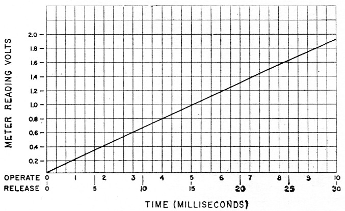
Fig. 2. Graph showing the relation between relay-functioning times using the circuit values of Fig. 1 The upper time scale applies when R3 is 68 kΩ, and is used in checking the "operate" time. The lower scale applies when R3 is 204 kΩ, and is used when checking "release" time. See text.
The resistors associated with the v.t.v.m. give a 10:1 voltage step-down for the conventional meter which has an input impedance of 11 megohms when the one-megohm probe isolating resistor is included. The voltage plotted in Fig. 2 is for the actual reading using this divider.
In measuring the operating-time difference between K2 and K3, connections 1 and 2 go to Y; and Y3, and 3, 4 and 5 go to Z2, Z1, and Z3, respectively. In measuring the release time between K3 and K2, connections 1 and 2 should go to Zl and Z2, while connections 3, 4, and 5 should go to Y3, Y1, and Y2, respectively. In checking the release time between K2 and K1, connections 1 and 2 should go to Y1 and Y2, while connections 3, 4, and 5 go to X3, X1, and 12, respectively.
In checking the release times, it should be pointed out, the timing capacitor will receive an initial charge if the 140 volt is applied to the circuit before the relays are energized to set them for a release measurement. Either the relays should be energized before applying the 140 volts, or the timing capacitor should be shorted to discharge it after the relays have been energized, just before making a measurement on release time.
The power supply used to operate the relays is the source of the 140 volt test voltage. Since this is a transformerless type of supply, care should be used during the test to be sure that the case of the v.t.v.m. does not become hot with respect to ground. Proper polarizing of the a.c. power plug will solve this problem.
Notes
- See "Fox, The fox vox adapter," QST, November, 1960.
Note: In Fig. 1, p. 19 of the November issue, R3 should be 1000 ohm.
Grady B. Fox, Jr., W2VVC.