Some applications of the semiconductor diode
Simplified keying and control circuits.
Anyone who scans literature in the electronic field soon becomes aware of the rate at which new uses are being found for semiconductors. Their small size and weight, low operating temperatures and freedom from the need for a filament supply make them attractive in a multitude of applications. Particularly when modifications are to be made in a piece of existing gear, it may prove worthwhile to consider the possibility of substituting semiconductors for vacuum tubes, since they do not require the cutting of new socket holes and in other ways often facilitate a job that would otherwise be impossible to accomplish.
One example of the many ways in which advantage may be taken of these features is the combined differential keyer and automatic powercontrol circuit shown in Fig. 1. The differential keying system (A) is based on a circuit described a few years ago by W5JXM.(1) In this instance, one of the vacuum-tube triode sections has been replaced with a 1N91 junction rectifier, CR1, while the v.t. triode section it replaces has been put to use in the power-control system (B).
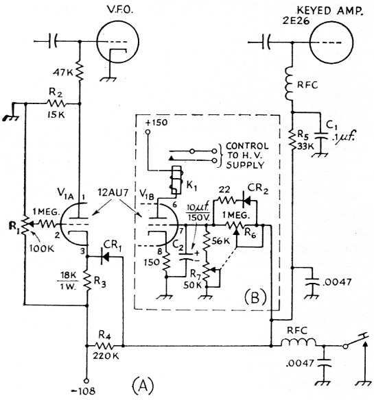
Fig. 1. Circuit of W6VAT's differential keying and control circuit. Capacitances are in µF; resistances in ohm. Resistors are ½ watt unless indicated otherwise.
| C1 | Poper or ceramic. |
| C2 | Electrolytic. |
| CR1 | 1N91 germanium rectifier (G.E., Sylvania). |
| CR2 | Silicon diode, 10 MΩ or more back resistance (Hughes Aircraft HR1021 1). |
| K1 | 10,000 ohm d.c. relay (Potter & Brumfield type LM). |
| R1 | 100,000 ohm control. |
| R2,R3,R4,R5 | See text. |
| R6 | 1 megohm control. |
| R7 | 50,000 ohm control. |
| V1 | See text. |
With the key open, bias on V1A is adjusted by means of R1 so that V1A draws plate current through R2 to cause a voltage drop across this resistor sufficient to cut off the oscillator. Capacitor C1 in the amplifier grid circuit charges to full supply voltage which is adequate to cut off the amplifier tube.
When the key is closed, current from the supply flows through R3, all but a small portion of it via CR1. This increases the drop across R3 sufficiently to cut off V1, the drop across R2 disappears, and the oscillator is turned on. R2 is now merely a part of the oscillator grid leak. Activation of the amplifier is delayed because CI must discharge through R5.
At the instant of opening the key, C1 will start to charge, the principal charging path at this instant being R3, CRI and R5. The charging current is in such a direction as to tend to maintain cutoff on V1A. However, as the voltage across C1 rises toward the supply value, the charging current will decrease and VIA will start to draw plate current which, of course, flows through the cathode resistor R3. This develops a voltage drop across R3 which is in opposition to the voltage charging C1. However, CR1 isolates the charging circuit from this opposing voltage to the extent that after a point in the charging cycle is reached where the voltage across R3 exceeds the voltage across R4, all charging current will flow through R4. Prior to this, charging current will flow in the two parallel branches in inverse proportion to their effective resistances. (The effective resistance of the CRI-R3 branch includes the effect of the opposing voltage due to VIA cathode current.) By suitable adjustment of R1, the proper delay between amplifier cutoff and oscillator cutoff may be obtained.
Control circuit
Another interesting application of the semiconductor diode is in the power-control circuit of Fig. 1B. Assuming C2 to be charged to a voltage that will cut off V1B with the key open, C2 will be discharged immediately upon closing the key, the discharge current flowing in such a direction that CR2 is conductive. The power relay therefore operates immediately. Upon opening the key, however, C2 must charge through R6, since the charging current is in such a direction that CR2 will not conduct. Therefore, the key must remain open for a certain length of time before K1 is de-energized. In this instance, CR2 must have a back resistance high compared to the value of the shunting resistance Rg. The , delay time may be adjusted over a wide range by means of R6. Since this adjustment will also affect the voltage to which C2 will ultimately charge, R7 is used to compensate for this. With R6 and R7 ganged to a single control, the capacitor voltage will remain more or less constant with adjustment of the time delay.
Simple Delay Circuit
Another circuit for which many uses may be found is shown in Fig. 2. In this circuit, both relays will be energized immediately when the switch is closed. However, upon opening the switch, Ki will be de-energized immediately, but K2 will not release immediately because C1 must discharge through R1 and R2 (with R3 and the resistance of K2 in parallel). The discharge current of C1 flows in such a direction that CR1 will not conduct, and therefore K1 is isolated from the delay circuit. The delay is adjustable from about one-half second to three seconds. If S1 is one pole of a keying relay, K1 may be used for muting the receiver in a break-in system, while K2 may be used for controlling the power supply.
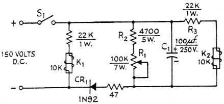
Fig. 2-Delay control circuit. Ki operates instantly on both make and break. K2 operates instantly on make, but the delay on break may be adjusted by Ri. Resistance values are in ohms.
| C1 | 100 µF 250 V electrolytic. |
| CR1 | G.E. 1N92 germanium junction diode. |
| K1,K2 | l0,000 ohm d.c. relay (Potter & Brumfield type LM). |
| R1 | 100,000-ohm 7-watt wire-wound control (Mallory El OOMP). |
| R2,R3 | See text. |
| S1 | See text. |
There are many other ways in which the crystal diode may be used, one of the more recent examples being the differential keying system described by W2HUG(2) in QST for April, 1959. And don't overlook the possibility of applying these devices in other circuits than those designed for keying and control. Their characteristics make them very useful in almost any circuit of the "go-no-go" type.
Notes
- Puckett, "'De luxe' keying without relays," QST, September, 1953.
- Reich, "Diode time-sequence keying for the DX-100," QST, April, 1959.
James G. Lee, W6VAT.