Fixed bias with audio a.g.c.
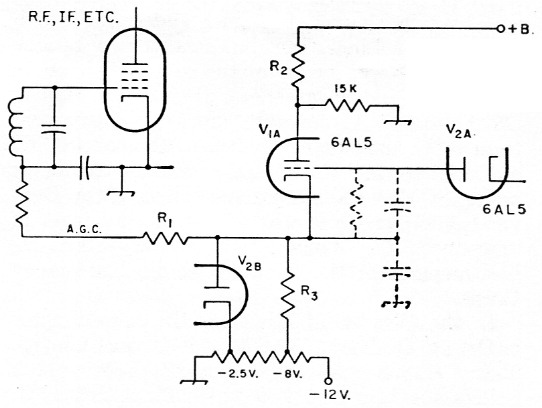
Fig. 1.
Regarding the article by W9IK, "An improved audio-driven a.g.c. circuit," in September QST, as an additional advantage this circuit can be modified so as to provide fixed bias to the grids of the a.g.c. controlled stages. This enables the cathodes of these tubes to be directly grounded, thus avoiding the use of cathode resistors and their attendant capacitors, which are only a source of noise. This method of applying a d.c. bias is not new but is becoming more popular; one recent receiver to employ it is the Geloso G209-R.(1) However, it is often difficult to apply without a lot of complicated switching and extra components, and this is especially true if separate a.m., s.s.b. and a.g.c. detectors are employed. It is, however, relatively simple to apply if the a.g.c. voltage is generated after the detectors.
In the circuit diagram shown in Fig. 1 of W9IK's article, only one half of a 6AL5 diode is used, and the other half can most usefully be employed to apply a d.c. bias through the a.g.c. line to the controlled tubes. The diode acts as a simple clamp for the cathode of V1A thus ensuring that at no time will the a.g.c. line go more positive than the fixed bias chosen for the tubes.
The take-off point for the a.g.c. can be adjusted to compensate for this added bias by the appropriate change in circuit parameters as mentioned in the article. The accompanying diagram shows these modifications and is self-explanatory.
Notes
K. W. Cranfield.