Modified "little oskey"
Keying monitor-receiver muter for low-level blocked-grid keying.
"Oskey" has been a popular c.w. accessory, but in its original form it was limited to, use with transmitters having cathode keying. Here's a method for adapting it to blocked-grid.
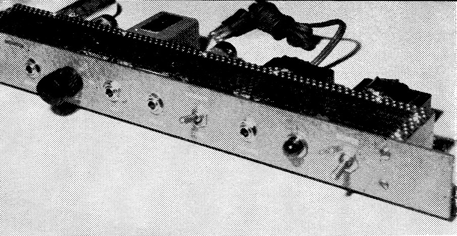
Assembled on a 1 unit rack panel, W1PKC's modified "Little Oskey" makes up into a compact strip that should fit in well with other equipment. Perforated aluminum is used for top and bottom covers for the chassis.
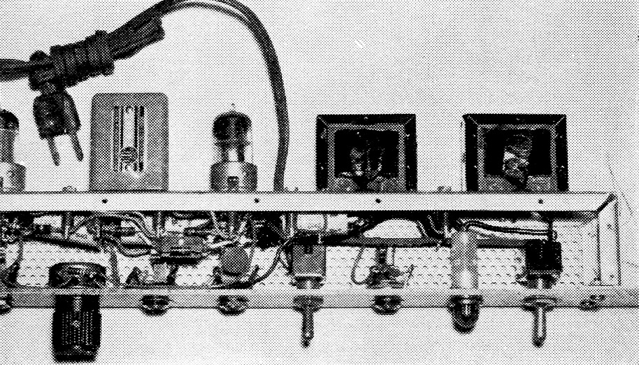
Plan view shows the arrangement of parts inside the chassis. The "Operate-zero" switch is at the center in this layout.
Little oskey(1) is an automatic switching monitor usable with any cathode keying system. As originally described, it blocked the receiver output while injecting a sidetone, keyed with the transmitter, into the phones. The system is fine for use with cathode keying of one or more transmitter tubes. However, it couldn't be used here because the rig uses blocked-grid keying of a silenced v.f.o. in which a Class-A buffer stage following the oscillator is keyed.
A check of the voltage at the key showed that the blocking voltage for the Class-A stage was in the vicinity of -27 volts. Since this voltage was obtained through a higa resistance between the negative supply and the grid, it was apparent that the slightest loading would reduce the voltage considerably. After the usual head scratching and some pencil pushing, the circuit shown in Fig. 1 worked out.
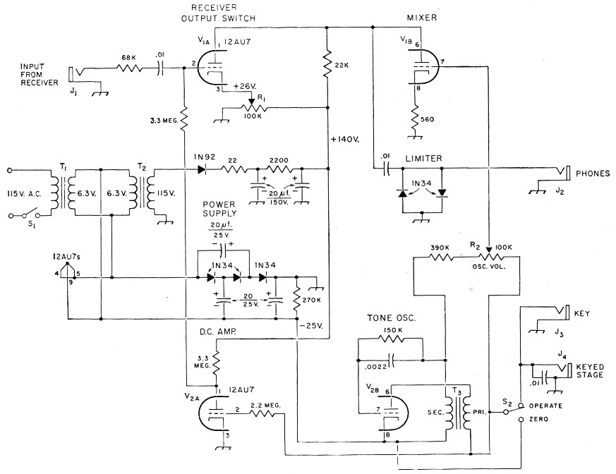
Fig. 1. "Little oskey" circuit modified for use with grid-block keying. Capacitances are in µF; resistances are in ohm, fixed resistors are ½ watt.
| J1,J2, incl. | Open-circuit phone jack. |
| R1,R2 | 100 kΩ potentiometer. |
| S1 | S.p.s.t. toggle. |
| S2 | S.p.d.t. toggle. |
| T1,T2 | Filament transformer, 6.3 volt, 1.2 A. |
| T3 | Interstage audio, secondary-to-primary turns ratio 2:1. |
The circuit
This arrangement uses the same receiver output switch and mixer circuits as "Little Oskey." The voltage tripler using the three 1N34s furnishes -25 volts to the cathode of the tone-oscillator tube, V2B. The plate circuit of this same tube receives a negative voltage through J4 from the keyed stage. Any volta 4e greater than -25 will work satisfactorily. In my setup it is -27 volts, so while the key is up the oscillator plate is 2 volts negative, and when the key is pressed the plate circuit goes to ground, which is then 25 volts positive with respect to the cathode. This is sufficient to trigger off the oscillator.
The same -27 volt from the key is applied to the d.c. amplifier (V2A) grid through the 2.2 megohm resistor. This grid voltage is sufficient to cause the voltage at the plate to be +25 volt with the key open, and when the key is pressed the plate drops to 15 volt. This voltage is applied to the grid of the switch tube, V1A, whose cathode is held at +26 volt by a voltage divider from the +140 volt line. Since the voltage excursion at the plate of V1A depends upon the voltage actually present at the open key terminals, a 100 k potentiometer, R1, is used to set the cathode of V1A approximately 2 volt positive with respect to its grid.
When keying, the voltage at the grid of the switch tube drops sufficiently to cut the tube off, practically, and no receiver output can be heard. The response of both the switch tube and the oscillator is fast enough so that a signal breaking in can be heard even through a series of dots. When first using this circuit there was some difficulty with key clicks generated within the monitor itself, but these were effectively eliminated by employing two crystal diodes wired back-to-back across the headphone output as shown. No distortion was noticed with the receiver gain set for normal headset listening, and a by-product of this limiting is the elimination of static crashes and the like.
The "zero-operate" switch, S2, enables the operator to key the transmitter without triggering the Oskey. This is useful when the v.f.o. is being keyed while tuning it to a desired frequency. In the "zero" position S2 disconnects the key from the monitoring circuit and applies -25 volt to the grid of V2A, allowing the receiver to operate normally while keying the transmitter.
Construction
No particular precautions need be taken when building this unit except for keeping receiver signal leads away from a.c. leads. The writer built his unit in a standard 13 inch relay rack panel, using a U-shaped chassis with screen top and bottom as shown in the photographs. J3 is marked "Input" on the panel, and is for a plug from the blocked-grid stage. The cathode-set potentiometer, R1, may be placed on the rear chassis apron since it need be set only once, when initially placing the monitor in operation. The two power supplies used are essentially copies of the original version(2) with the exception of the 1N92 diode employed for the +140 volt supply. The 1N92 was used here to conserve space: a low-current selenium rectifier would do just as well.
Using it
The jacks are practically self-explanatory: Receiver output is plugged into the "Receiver Output" jack, headphones into the "Phones" jack, and the key and keyed stage into their proper jacks. Turn the unit on and, using a 20 kΩ/V meter or a v.t.v.m., measure the voltage at the grid of V1A. Next, adjust R1 so that the voltage at the cathode of V2A is one or two volts more than at the grid. With the receiver feeding a signal into the input, the signal should be heard in the phones. Key the transmitter and adjust the oscillator gain control for comfortable sidetone volume.
Notes
- Campbell, "Little oskey," QST, October, 1955; also, The Radio amateur's handbook, 1959 edition, keying chapter.
- Since the positive voltage is not especially critical, there appears to be no special reason why the power-supply circuit could not be simplified considerably and made more economical by using a "TV booster" transformer (typically 125 volt at 20 mA, and 6.3 volt at 0.6 A) in place of the two filament transformers. A voltage divider across the rectifier-filter output could be grounded at the proper point to give -25 volt for the bias circuit. This would eliminate one transformer and the separate rectifier-filter. - Editor.
Frank Blanchette, W1PKC.