Surplus tubes + an old tv set = 150 Watt amplifier
A couple of articles have shown the popularity of using old TV sets as a source for amateur parts. Here is a do-it-yourself project combining the old TV set with surplus tubes and ending up with a 150 watt multiband amplifier. The cost? - something less than 20 cent a watt!
When a novice graduates to the General-Class ranks one of the first things he thinks about is more power. If you are in this class, the unit described in this article may be right up your alley. The amplifier described here can be run at inputs up to 150 watt and can be built for about $25.00, including power supply.
Usually the most expensive item in an amplifier is the power supply. In the unit described here this cost was held to a minimum by using power-supply components taken from an old TV chassis. As has been pointed out in two previous articles,(1) an old TV set is one source of low-cost parts for the enterprising amateur. The other expensive item in an amplifier is the amplifier tube or tubes. This item was taken care of by using surplus 1625s, a 12 volt version of the 807. The 1625 can be run at a maximum plate voltage of 750 and a plate current of 100 mA, or 75 watt input per tube. However, if you happen to own some 807s, they can be used instead of the 1625s merely by using five-pin tube sockets instead of the seven-pin ones required for 1625s, and putting 6.3 volts on the heaters.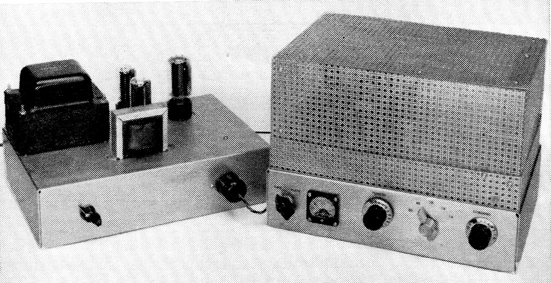
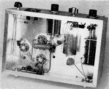
Over-all view, both units, showing the completed power supply and amplifier. The switch on the left front of the power-supply chassis is S3. On the amplifier, from the left, the controls are the meter switch, plate tuning, band switch, and loading control.
Circuit description
The circuit of the amplifier is shown in Fig. 1. Two parallel-connected 1625s - about 35 cents each on the surplus market - are used in the unit. Another 1625 serves as a clamp tube to provide protection for the amplifier tubes when excitation is removed.
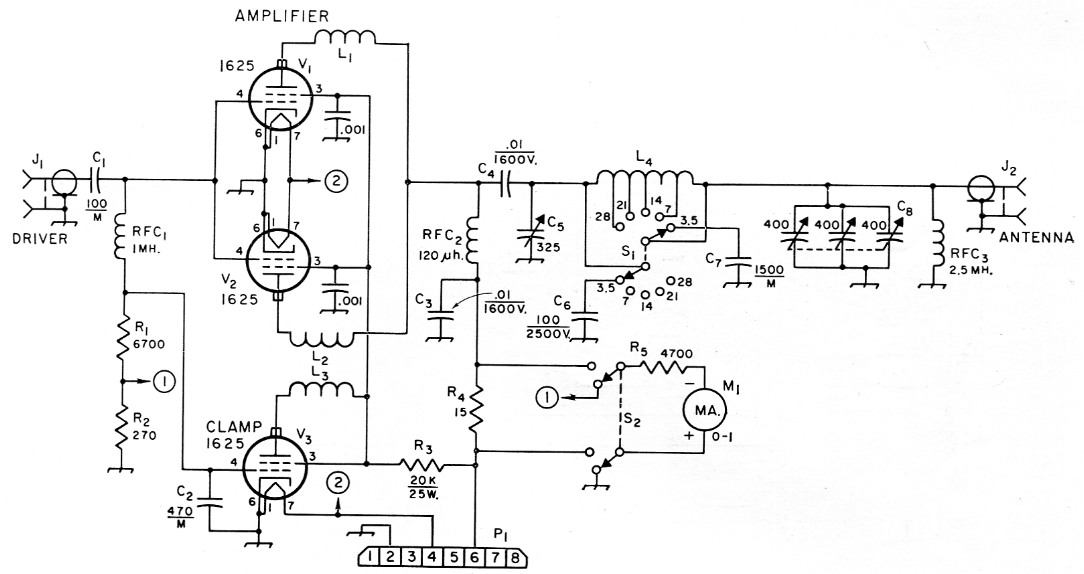
Fig. 1. Circuit diagram of the 1625 amplifier. Unless otherwise indicated, decimal values of capacitance are in µF, others are in pF; M = mica. Resistances are in ohm.
| C1 | 100 pF mica. |
| C2 | 470 pF mica. |
| C3,C4 | 10 nF 1600 volt disk ceramic. |
| C5 | 325 pF variable (Hammarlund MC-325-M). |
| C6 | 100 pF mica, 2500 volt. |
| C7 | 1500 pF mica. |
| C8 | Three-section receiving variable, approx. 400 pF per section (Allied Radio 60-H-726 or Philmore 9047). |
| J1,J2 | Coax chassis receptable type S0-239. |
| L1,L2,L3 | 10 turns No. 18 enam., close-wound on a 1 watt resistor, 1000 ohm or more. |
| L4 | 19 turns No. 14, 1½ inch diam., 9 turns spaced 12 turns per inch, 10 turns spaced 6 turns per inch (Illumitronic Air Dux 121 D6). The end of the coil with wide spaced turns is connected to C5. 7 Mc tap: 12 turns from the C5 end of the coil. 14 Mc tap: 6 turns from the C5 end of the coil. 21 Mc tap: 4 turns from the C5 end of the coil. 28 Mc tap: 2 turns from the C5 end of the coil. |
| M1 | 0-1 milliammeter, 1_5/8 inch square, D'Arsonval movement. |
| P1 | Octal plug (Amphenol 86PM8). |
| R1 | 6700 ohm, 1 watt. |
| R2 | 270 ohm, ½ watt. |
| R3 | 20,000 ohm, 25 watt. |
| R4 | 15 ohm, ½ watt. |
| R5 | 4700 ohm, ½ watt. |
| RFC1 | 1 mH (Millen 34300-1000, National R-50). |
| RFC2 | 120 µH, 500 mA (Raypar No. RL-101). |
| RFC3 | 2.5 mH (Millen 34103, National R50). |
| S1 | Ceramic rotary, 1 section, 2 poles, 5 positions (Centralab PA-2003). |
The grid circuit of the amplifier is untuned, and while this requires slightly more driving power than a tuned circuit, nearly any existing Novice rig will furnish more than enough drive on all bands.
When there is no drive to the amplifier the grid of the clamp tube, V3, is at zero voltage and V3 will conduct. When V3 conducts, the screen voltage to V1V2 is pulled down from its normal operating level of about 300 volts to less than 100 volts. When the screen voltage on the amplifier tubes drops this low, the plate-current flow through the two tubes is sharply reduced and the tubes idle at well below their rated plate dissipation. When excitation is applied, the grid-current flow in V1V2 develops enough grid bias to cut off V3, so that the clamp tube no longer conducts and the screen voltage on V1V2 rises to its normal operating value.
A switchable pi-network tank circuit covering 80 through 10 meter is used in the amplifier. The network is designed to work into 50-to-70ohm loads. The band switch, S1, is a double-pole unit with one pole used for shorting out unused portions of L4 and the other pole for adding capacitance (C6) across C5 when tuning 80 meter. The output loading capacitor is a three-section variable of about 400 pF per section, with all sections connected in parallel. On 80, an additional 1500 pF mica capacitor, C7, is connected across C8 by means of S1. RFC3 is a safety precaution to short-circuit the d.c. to ground in the event the plate blocking capacitor, C4, should short out.
A 0-1 milliammeter, connected as a voltmeter, is used to measure either the plate or grid current. It does this by measuring the voltage drop across shunts of appropriate resistance, R2 in the grid circuit and R4 in the plate. The full-scale current is 20 mA when the meter is switched across R2 and 300 mA when connected across R4 in the plate lead.
Power supply
A bridge rectifier circuit, Fig. 2, is used in the power supply in order to obtain the highest possible +B voltage from the transformer. The circuit consists of a pair of 6DE4s and a 5U4G rectifier with a choke-input filter. The choke, L5, is a 2 henry job taken from the TV set. Two 30 µF 500 volt electrolytic capacitors are connected in series to provide a working voltage of 1000 volt. The +B voltage can be turned on and off with S3B. Another section, S3A of the same switch, is used to turn the supply on and off. P2 is a fuse-in-plug unit with F1 and F2 being used to protect the supply in the event of overload.
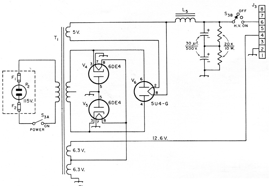
Fig. 2. Circuit diagram of power supply.
| F1,F2 | 3 A type 3AG. |
| J3 | Octal socket. |
| L5 | Approx. 2 H, taken from TV set. |
| P2 | Line plug, fuse-in-plug type. |
| S3 | Single-pole, four-position with a.c. switch on back (Centralab 1465). |
| T1 | Power transformer taken from TV set; see text. |
Nearly all TV transformers have at least two 6.3-volt filament windings. These windings can be connected in series to provide the required 12.6 volts for the 1625 heaters. The 6.3 volts required for the 6DE4s is taken from one of the two 6.3 windings; use the winding with the heavier current rating (heavier wire) for this purpose if there is a choice.
In our case, the TV power transformer came from a 1950-vintage TV set. This particular transformer is rated at 365 volt a.c. each side of center at about 300 mA. In addition to the two 6.3-volt windings there is also a 5 volt winding that is used for the 5U4. The +B voltage you end up with will, of course, depend on the transformer used in the TV set you scrounge. In any event, the d.c. voltage out of the filter should run somewhere between 550 and 750 volt. The latter figure is the maximum plate voltage rating for the 1625 or 807.
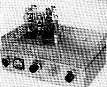
Amplifier, top removed. The three 1625s are shown at the left-hand side of the chassis in this top view. Note that the parasitic suppressors Li, L2, and L2 are mounted directly at the plate caps. The coil to the right of the tubes is RFC2.
Construction details
The amplifier was built on a 3 × 8 × 12 inch aluminum chassis, with the power supply as a separate unit. If desired, the builder can combine both units on a single chassis, but a larger one would, of course, be required.
The bottom-view photograph will show you most of the layout details. The three 1625s are mounted at one side of the chassis and most of the rest of the room is taken up with the tank circuit components. An Air Dux 1212D6 coil assembly is used for L4. This assembly is supported on the chassis by two 1¼ inch high isolantite standoff insulators. The tap leads for the various bands are brought forward to S1, which is mounted on the chassis front between C5 and C8.
Bottom view. Here are the works below deck. The clamp tube socket is at the for left in this view, with the two amplifier sockets to the right. The La assembly is mounted on two standoffs, the assembly being positioned between Cs on the left and Co at the right. On the back of the chassis is is at the left side and J2 at the righthand side, in this view.
If TVI is likely to be a problem in your area, then the amplifier should be shielded to reduce harmonic radiation. The shield shown in the photographs was made from Reynolds do-it-yourself perforated aluminum stock. The shield shown with the unit is made to slip down inside a "fence" that runs around the chassis top. The fence is made from two sections of the perforated stock, 2 inches wide and 21 inches long. The perforated stock comes in a 36 × 36-inch piece, so it is impossible to get a single length long enough to go around the entire chassis. The completed fence is 1% inches high with a %-inch lip which is secured to the chassis by machine screws and nuts. The two sections are each formed into an L shape measuring 1 × 8 × 12 inch, the one-inch portion being used at two of the corners as an overlap to fasten the two sections together with screws and nuts.
Two pieces of the stock measuring 6½ × 20¾ inches before folding are used for the sides of the shield. The side dimensions of the two pieces after folding are 7_7/8 and 11_7/8 inch; the extra inch is used for the overlap to connect the two pieces together. A one-inch flange is folded in around at the top so that the over-all height is 5½ inch. The top is made from a piece of stock 7_7/8 by 11_7/8 inch and is secured to the top flange with nuts and screws. The completed cover can be slid down inside the fence and flush with the chassis. The overlap of the fence and sides should prevent harmonic leakage if care is taken to see that the two have a snug fit. To complete the shielding a bottom plate should be installed on the chassis.
As it comes, the coil L4 has more turns than are needed. Remove 17 turns from the close-wound end of the unit, which will leave a total of 19 turns. In order to prevent shorting out turns when installing the 40-meter tap, the turns adjacent to the 40-meter tap point should be bent in toward the center of the coil. The remaining taps are on portions of the coil where the turns are not so close together so there shouldn't be any danger of shorting turns when making the taps. See Fig. 1 for additional information on the coil.
The coils L1, L2 and L3 in the plate leads of the three tubes are for v.h.f. parasitic suppression. These coils should be mounted directly at the plate caps. The coils are wound on one-watt resistors, with the resistors only being used for forms so any resistance value greater than 1000 ohm is suitable.
When wiring the power supply, just "tack" the 6.3 volt heater connections together. If you should connect the two windings the wrong way, the voltages will buck each other and instead of getting 12.6 volt you'll get zero. You can make the permanent connection once you find out which way is correct. The simplest way to do this is to connect the power supply to the amplifier and try the supply. If the heaters on the 1625s light up then you know you have the connections correct. When the supply is completed you are ready to test the amplifier.
Testing and tune up
Connect the power supply and your exciter to the amplifier. You can use a short length of coax cable - either the 50 or 70 ohm type is suitable - between the exciter and amplifier, but keep the length of coax as short as possible. You should use a dummy load on the amplifier and a 100 watt lamp bulb will be suitable. Turn on the power supply, but leave the +B off (second position of 83) and let the heaters warm up. Switch the exciter and the amplifier to 80 meter and turn on the exciter. With the amplifier meter switched to read grid current, tune the exciter for a grid reading of 8 mA. You'll probably find that your exciter is very lightly loaded when you get the 8 mA grid current. Next, switch the amplifier meter to read plate current, set Cs at maximum capacitance, plates fully meshed, and turn on the +B voltage. Resonate the amplifier by tuning C5 for a dip in plate current reading. You can now start to load the amplifier by decreasing the capacitance of C8 and retuning C5 for a dip as you continue to increase the plate current. The lamp load should light up and increase in brilliance as the amplifier is loaded. Maximum plate current is 200 mA, or two-thirds of full-scale reading.
Be careful in loading up the bulb if you have 750 volt on the plates of the amplifier, because if you go too far you might burn out the lamp. The same procedure should be followed for checking on the other bands.
With the power transformer used in the unit shown here, the plate voltage under load was 720. Screen voltage was 300 volt. When excitation is removed, the screen voltage drops to less than 100 volt. In order to get maximum output from the 1625s, the screen voltage should be about 300 volts when drive is applied to the amplifier. If you should have a power transformer that gives you only somewhere near 600 volt under load, then the screen-dropping resistor R3 should be less than 20,000 ohm. A 15,000 ohm 25 watt unit will give a screen voltage of about 300 with a plate voltage of about 600. We say "about" because a variation of plus or minus 20 volt would not materially affect the performance of the amplifier.
One other thing the Novice usually wants when getting his General-Class ticket is a v.f.o. As pointed out earlier, this amplifier requires a few watts of drive but it should be stated here that the average commercial v.f.o. does not have enough power to drive the amplifier. In order to drive the amplifier and use a v.f.o., an intermediate stage would be required.
Notes
- McCoy, "75 watt novice - 100 watt general," QST, Sept., 1959
"65 watt at low cost," QST, March, 1961.
Lewis G. McCoy, W1ICP.