An evaluation of the nuvistor
Comparing the 6CW4 with conventional tubes at 50 to 450 Mc.
By now most v.h.f. men who build their own receiving gear, and some who don't, have been wondering about the Nuvistor, a radically different type of tube introduced some time ago by RCA. Advance information indicated that the 6CW4 should be a very good performer in the v.h.f. range,(1) and perhaps even at 420 Mc. As the tube is now becoming available commercially, and at moderate cost, we wanted to find out just what it would do in comparison with the tubes we've been using in v.h.f. front ends for some years. Some finished models of v.h.f. converters using Nuvistors will be ready for description in QST before long, but meanwhile here are bits of evidence as to what can be expected from them.
The quickest way to see what Nuvistors would do was to start with converters of conventional design and known performance, and install Nu-vistor r.f. stages in them. Our family of v.h.f. converters appearing in the Handbook for the past several years served as the guinea pigs for this experiment. We will discuss them in the order in which they are described in the Handbook text.
50 Mc
Optimum converter performance at 50 Mc. is no problem, at least as far as noise figure is concerned. External noise being what it is at this frequency, almost any tube will give a better noise figure than is needed. Our Handbook 50-Mc. converters have for some years featured pentode r.f. stages, admittedly having higher noise figure than the better triodes. We even threw away some more noise figure in the most recent model by putting in extra tuned circuits in the r.f. stage, with the idea of improving its freedom from overloading by TV and other strong signals on frequencies adjacent to the band.
As expected, the Nuvistor provided far lower noise figure at 50 Mc. than the 6CB6 used in the original design. A single 6CW4 neutralized stage, as shown in Fig. 1, gave more than enough gain to override mixer noise. The circuit is the same as would be used in the first half of a cascode stage, but the second triode is omitted. (You could get a still lower noise figure by using the second tube, but why bother when one 6CW4 gets down to 4 db. or so easily?) The stage was first used with the tuned circuits exactly as shown in the Handbook, except for the addition of a neutralizing coil. It was also tested using the single-tuned input circuit, as in Fig. 1. Naturally, this gives a broader response, and somewhat less attenuation of out-of-band signals than the double-tuned circuit of the Handbook.
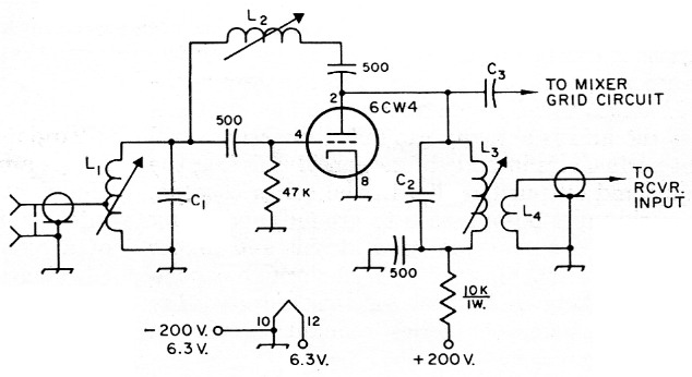
Fig. 1. Circuit diagram of a neutralized triode r.f. amplifier using the Nuvistor. Capacitor values in pF. Values of components not given depend on frequency. L4 is used only in a separate preamplifier.
| C1 | 50 Mc: 10 pF fixed ceramic. 144 Mc: 8 pF trimmer. 220 Mc: 5 pF trimmer. |
| C2 | 10 pF fixed ceramic for 50 Mc.; not used on 144 and 220. |
| C3 | 1 to 2 pF. May be made by twisting plastic-covered No. 18 wires together about 1 inch. |
| L1 | 50 Mc: 11 turns No. 24 enam., close-wound on ¼ inch iron-slug form. Tap at 3 turns. 144 Mc: 4 turns No. 18, ¼inch diam., ½ inch long, air-wound. Tap at 1½ turns. 220 Mc: 3 turns No. 18, ¼ inch diam., 1/4 inch long. Tap at 1 turn. |
| L2 | Iron-slug coils, nominal inductance given. 50 Mc: 3.3 µH. 144 Mc: 0.68 µH. 220 Mc: 0.22 µH. (Miller 20A336RBI, 20A687RBI and 20A227RBI, respectively). |
| L3 | 50 Mc: Same as L1, but no tap. 144 Mc: Same as L1, but 5 turns, no tap. 220 Mc: Same as L1, no tap. |
| L4 | 50 Mc: 3 turns around L3. 144 and 220 Mc: 2 turns. |
Next a 6CW4 was installed in the mixer. This gave lower mixer noise than the pentode it replaced, and brought the over-all noise figure down to about 3 db. This is several decibels better than you'll ever need, so adjustment is a breeze. Just peak the circuits for maximum response at the portion of the band you favor, or stagger-tune them for broader response across the band. Either way you'll have a front end that is a lot better than you can use. To prove this for your own satisfaction, put a 50-ohm resistor across the input, and observe the noise. Now put your antenna on, and watch the noise shoot up at least 4 db. This is your margin of performance, beyond which you gain nothing in weak-signal reception by tinkering with the front end.
If you have one of the commercial receivers that tunes 50 Mc., but does so with less than optimum front-end performance, a Nuvistor r.f. preamplifier like the one shown in Fig. 1 will make it "come alive" in a fairly convincing manner. Follow the circuit, but drop C3 and add L4 around the plate coil, L3, to couple into coax running to the receiver input terminals.
144 Mc
We spent more time on 144-Mc. Nuvistor circuits than with those for the other bands. With the help of W1DXE, we tried grounded-grid, series cascode and conventional cascode stages, in several different converters. There seemed to be little choice between them, except that the cascodes were easier to tame. In the Handbook converter, substitution of a 6CW4 for the first 6BC4 netted an appreciable improvement in noise figure. The circuit was similar to Fig. 1, except that the plate coil was resonated with the tube capacitance only, and air-wound coils were used instead of slug-tuned ones. The capacitor across L1 was made a sleeve-type trimmer.
An interesting complication was encountered with the series cascode: the second (or grounded-grid) half of the cascode oscillated very readily. This can be confusing; you assume that oscillation must be in the first stage, and you knock yourself out trying various sizes of neutralizing coils, to no avail. After several frustrating hours of this it dawns on you that the trouble is in the grounded-grid portion. Oscillation in grounded-grid stages usually comes from the fact that unless the grid is actually grounded directly it will not perform its intended function of isolating the input and output circuits. In the series cascode, the grid must be bypassed to ground, and many capacitors are none too good at this and higher frequencies. Button-type or feed-through capacitors are likely to be best for this purpose. Try tunable bypasses or series-resonant circuits in troublesome cases.
The net result of our work on 144 Mc. to date is that the 6CW4 shows up as the best low-cost tube available for r.f. amplifier service. It is ahead of the 6BC4, 6AM4, and the like, and it is as good as all but the hottest 417As. It is almost certain to be better than the "retired" 417As that most hams have available - and it very likely will last longer than the new ones.
220 Mc
It was on this band that the 6CW4 really be- gan to pay off. Here we are almost completely above the frequency where external noise is a factor in weak-signal reception. We are also above the optimum working range of most available tubes. The compact structure and high transconductance of the Nuvistor make for real improvement in 220-Mc. reception, compared to conventional tubes.
First we made a trough-line grounded-grid r.f. amplifier with a 6CW4. This was a duplicate of the one in the Handbook converter for 220, except for the circuit differences shown in Fig. 2. When installed in place of the 6AM4 amplifier originally shown, it dropped the noise figure by nearly 3 dB, a marked improvement in weak-signal reception, with a converter that was already fairly good, as 220 Mc converters go.
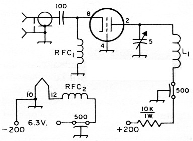
Fig. 2 Circuit diagram of the Nuvistor 220 Mc grounded-grid amplifier.
| L1 | Inner conductor of trough line. See Handbook, 19581961. |
| RFC1,RFC2 | 1.1 µH solenoid r.f. choke (Waters C1001), or 22 turns No. 26 enamel close-wound on a 1 watt resistor. |
The next step was a preamplifier using essentially the circuit of Fig. 1. This was a surprise, in that it turned out better than the grounded-grid stage, as far as ease of adjustment was concerned. Used ahead of a commercial 220 Mc. converter having a 6BZ7 cascode front end, it made a 5 dB improvement in noise figure. This is enough to make easily-readable signals out of some that were all but buried in the noise before.
432 Mc
To date, the only Nuvistor stage tried on 432 Mc is a preamplifier similar to that shown in the Handbook, where a 6AJ4 or 6AM4 is used. This is intended for use as a separate preamplifier, ahead of a converter such as those presently using no r.f. stages. Though not completely stable in its present form, it does not oscillate when it is heavily loaded by the succeeding stage, and by the antenna. As might be expected where regeneration is present, the gain is very high. Used ahead of an excellent crystal-mixer converter having no r.f. stage, it makes an observable improvement in weak-signal reception. We have more work to do before we can say that we have an entirely satisfactory 6CW4 r.f. stage at 432 Mc, but initial results certainly are promising.
Some general observations
The Nuvistor is a low-voltage device, compared to conventional vacuum tubes. Typical operation calls for a plate voltage of 70. It is recommended that this be taken from a supply of higher voltage, with a relatively high value of dropping resistor, as shown in our diagrams. This gives better characteristics as to overloading than running the stages with a supply voltage of 70. Up to 300 volt may be used, provided a sufficiently large value of dropping resistor is employed.
The cathode is normally grounded instead of running it to ground through a bias resistor, as is done with most tubes. The grid can be operated in two ways. Where it is desirable to ground the grid directly, as in Fig. 2, the plate voltage should be adjusted by means of the dropping resistor so that the plate dissipation is held to under 1 watt, maximum. This will mean that the voltage at the plate may have to be 60 volt or less, to avoid excessive input. Where a grid leak and blocking capacitor are used, as in Fig. 1, plate current will be lower, and the permissible plate voltage higher. The maximum of one watt of plate dissipation is the point to watch in either case. Nuvistors work well with as little as 40 volts on their plates.
In grounded grid circuits there is a marked tendency to oscillation, due to the grid not being completely at ground potential. Even with the grids connected to ground with the shortest possible leads, our 220 and 432 Mc trough-line stages are a bit more touchy than they should be. As mentioned in connection with the 144 Mc cascode stage earlier, watch the capacitor used to bypass the grid, in stages where the grid is above ground for d.c. We found that a type of mica capacitor, not generally available in stores handling the usual parts lines, was very good for this purpose. It had a silver-plated flat housing that could be soldered directly to the chassis, and a wide flat lead to the capacitance element. The capacitance was 260 pF. When connected to the grid of W1DXE's wildly-oscillating second half of a series-cascode amplifier, it calmed it down beautifully, and made it work as a grounded-grid stage should. The little disk ceramics are not much good as bypasses at 144 Mc.
We have not yet completely tamed the 220 and 432 Mc trough-line amplifiers. These have the grid pins of the sockets connected directly to the copper troughs, but they're still hot for r.f. Possibly a series-resonating tuned circuit would do the job better, but we've been waiting for a different type of socket before trying this. Several types of sockets have been made for Nuvistors, including some having paralleled lugs for the r.f. circuit connections. Possibly these would make the grid lead inductance low enough to bring the stages closer to true "grounded-grid" status. The sockets have not yet become available, so we'll have to wait to find out.
For reasons cited above, we now lean toward neutralized stages like that of Fig. 1. If the neutralizing coil L2 is made variable, adjustment of the stage is done very easily. Simply set up the converter for normal operation, but with the plate voltage disconnected from the stage to be neutralized. Feed a strong signal into the antenna jack, and adjust the core of L2 for minimum signal. This should be done with the converter or r.f. amplifier in the position in which it will ultimately be used, and with all shielding in place. Now apply voltage and adjust all circuits except L2 for maximum signal, at the middle of the range you expect to work over. Disconnect the plate voltage and reset L2 for minimum signal again. Reconnect the plate supply, and adjust the input circuit for best signal-to-noise ratio, which is not necessarily the same as for maximum gain. Now relax - you've got an excellent r.f. stage going for you, in the never-ending struggle to hear something that your friends miss.
Notes
- "The nuvistor as an r.f. amplifier at 144 Mc," QST, Sept., 1960, p. 38.
Edward P. Tilton, W1HDQ.