Coaxial transformer for voltage-fed antennas
A quarter wavelength of coax cable makes a good weatherproof transformer for matching a coax line to an end-fed antenna. The author uses it to feed a half-wave beer-can vertical on 20 meters.
Simple matching device for coax feed.
According to a famous saying, many roads lead to Rome. In matching an antenna there are also many roads or approaches one can take. In a previous article(1) the author described a matching unit for an end-fed halfwave vertical radiator, constructed of a coil and capacitor. Although the electrical performance of that matching unit was almost ideal, certain mechanical features were not.
Matching system
Fig. 1 shows the basis for an improved matching device. The shorted quarter-wave coax cable at the left is electrically equivalent to the coil and capacitor of the parallel resonant circuit to the right. For a design frequency of 14.1 Mc, the length of coax cable needed is 11 feet 6 inch. If your radiator is not precisely a half wave long (and it need not be), it will be either capacitive or inductive, depending on whether it is slightly shorter or longer, respectively, at the design frequency. This is of no consequence, for the resultant susceptance of the stub and the radiator will automatically be cancelled during the tuning procedure. However, the length of the coax section should be made longer to allow for this.
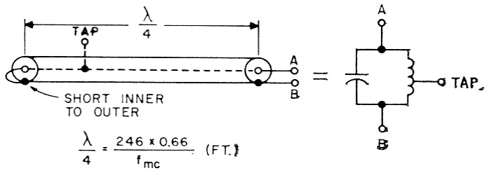
Fig. 1. A shorted quarter wavelength of transmission line is equivalent to a parallel-tuned circuit. A match is obtained in either case by connecting the feed line at a tap point. The factor 0.66 is the velocity factor of the line used for the matching section.
Adjustment
A grid-dip oscillator and a standing-wave bridge will be needed and they will be used in the same manner as described in the previous article.(1)
First, solder the inner conductor (point A) of the coaxial transformer to the radiator, and the outer conductor (point B) to the ground system. Now measure 26 inch from the shorted end and remove a half-inch-wide band of the vinyl jacket (see Fig. 2). Spread the braid carefully to expose a spot on the polyethylene inner insulation. Solder a sewing needle to the exposed end of the inner conductor of your feed coax coming from the transmitter. Insert this needle through the prepared opening in the exposed braid of the stub so that it makes contact with the inner conductor. Now spot-solder the feed-line coax and stub braids together. Excite the line from the transmitter with the g.d.o., and read the s.w.r. bridge.
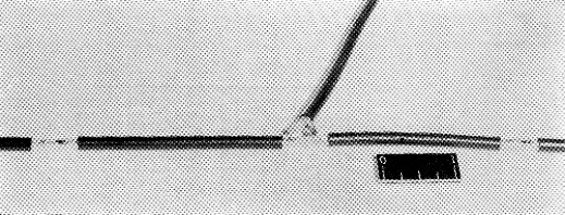
Fig. 2. The correct tapping point for the transmission line is determined experimentally by probing the center conductor of the matching section with a needle. Bared spots to right and left are additional check points.
If you're lucky, the reading will be close to a null (no reflected voltage). If not, then make an adjustment on the length of the coaxial transformer by inserting a second needle approximately one inch from the shorted end, making sure that it is shorting the braid to the inner conductor. Repeat this adjustment, moving the short an inch at a time, as long as it improves the bridge null. Then make a similar adjustment on the location of the tap by moving the first needle approximately 3 inches either way, after baring two new spots as shown in Fig. 2. This will show in which direction the tap should be moved, and the final adjustment can be made by trying the tap at smaller intervals.
When a bridge null is obtained and the g.d.o. dips best at the design frequency, carefully measure the dimensions C and D of Fig. 3, and make up a new cable as shown.
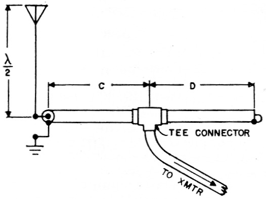
Fig. 3. After the correct tap point has been determined, lengths C and D are measured and the permanent matching section is made up using a coax T connector at the tap point.
Materials
The author used 50 ohm coax cable throughout. The coaxial transformer section is RG-58/U. There was no sign of voltage arc-over using a DX-100 with 175 watt input. For higher power, it is recommended that RG-8/U be used. When the coaxial transformer is completed, the open ends should be sealed with plastic tape; then it can be wrapped into a coil and practically hidden from view. (See Fig. 4.)
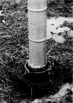
Fig. 4. The completed matching transformer may be wound up into a compact coil around the base of the antenna.
In conclusion, the coaxial matching transformer, by virtue of its physical configuration, greatly improves resistance to the effects of rain, snow, or little children, without sacrificing electrical performance. The author's unit has been in service for over a year and has proved to be a reliable and worthwhile improvement at W2JTJ.
Notes
- Czerwinski, "The 'Budget' vertical on 20 meter," QST, September, 1960.
W. Pete Czerwinski, W2JTJ.