High-accuracy channels at 3 kc intervals
Technical Editor, QST:
W2AOE's plan for channel-type phone operation(1) suggests a possible new method of frequency control for amateur transmitters and receivers. I have devised a system for generating a signal on any of his 50 channels in the 75 meter phone band using a minimum number of crystals. The circuit automatically compensates for v.f.o. drift and produces a signal exactly on frequency in any channel - simply by tuning the v.f.o. near that channel.
The principle of operation is not unlike that used in the Racal RA-17 receiver.(2) A 4 kc oscillator is used to drive a harmonic generator (Fig. 1). The harmonics lying between 200 and 400 kc are heterodyned to 3 Mc where they are fed into a filter which will pass only one of the 4 kc spaced signals at a time. The particular harmonic being used is determined by the v.f.o. frequency. Simultaneously the v.f.o. signal is fed to a balanced mixer where it is combined with 4199 kc from a crystal oscillator to give a sum frequency between 6799 and 6999 kc, depending on the v.f.o. setting. This is finally combined with the 3 Mc signal in the last mixer, where the difference frequency will be on one of the desired channels between 3799 and 3999 kc.
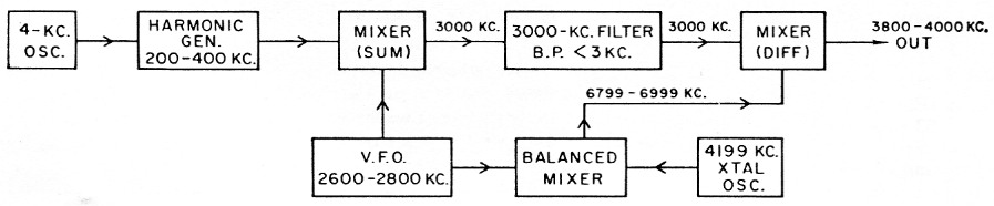
Fig. 1.
That any reasonable amount of v.f.o. drift will have no effect on the output frequency can be seen by the following example: Assume that the v.f.o. is set to 2788 kc and thus beats with the 4 kc harmonic on 212 kc to give the sum frequency of 3000 kc in the center of the filter pass band. The same v.f.o. frequency beats with 4199 kc from the crystal oscillator to give a sum frequency of 6987 kc, and this in turn is mixed with the 3000-kc. output of the filter to obtain the final difference frequency of 3987 kc. If the v.f.o. drifts to 2789 kc, the sum with 212 kc will be 3001 kc, the sum with 4199 kc will be 6988 kc, and the difference between 6988 and 3001 kc will still be the same channel frequency, 3987 kc. The only effect on the output signal is a variation in amplitude, since 3001 kc will be on a different part of the filter response curve.
The principal precautions to be observed with this system are (1) preventing spurious signals from appearing in the output, especially the 4199 kc crystal-controlled signal because of its closeness to the desired output frequency, and (2) preventing more than one of the 4 kc interval signals from passing through the filter at one time, for any v.f.o. tuning condition. The latter means that the filter attenuation should be very high when the v.f.o. is tuned midway between frequencies that give maximum output through the filter; i.e., the filter transmission should be negligible at 2 kc either side of its band center.
Because of school work the writer does not have an opportunity to try out the method at present, but it would appear to offer a fairly simple way of getting accurately-spaced channel frequencies with a minimum of exnensive equipment.
Notes
- Griffin, "A plan for improved utilization of amateur phone assignments," Technical correspondence, QST, May, 1960.
- "A new receiver tuning principle," QST, March, 1958.
John A.Wick, K0HKI.