Understanding tetrode screen current
Significance in R.F. amplifier adjustment and operation.
This article discusses the behavior of screen current in a tetrode ri. power amplifier using fixed screen voltage, and explains why a screen-current meter is a better indicator of operating conditions than a plate-currentmeter. Particular reference is made to the adjustment of AB1 linear amplifiers.
Perplexing screen-current behavior has probably disturbed many amateurs, particularly single-sideband operators. The need for a thorough discussion of the subject has prompted this article. Class AB1 operation has been chosen for discussion because of its current popularity as a means of achieving good linearity and TVI free operation. The information given herein assumes grid-driven conditions, but it applies equally well to cathode-driven tetrodes operated Class Aril with normal d.c. voltages on the grid and screen, provided that grounded-grid characteristic curves are used for computations.
Screen characteristics
Fig. 1 shows a set of constant-current characteristics for a typical 4CX300A. The term "constant current" is used because the lines plotted are lines of constant plate, screen, or grid current. The grid-voltage scale appears on the left axis and plate voltage is shown horizontally. These curves depict instantaneous values of plate and screen current for any given grid- and plate-voltage condition. In this reproduction, the grid-current lines are omitted because grid current is not drawn in Class ABl operation. The curves are valid only for a fixed screen voltage (350 volt in this case).
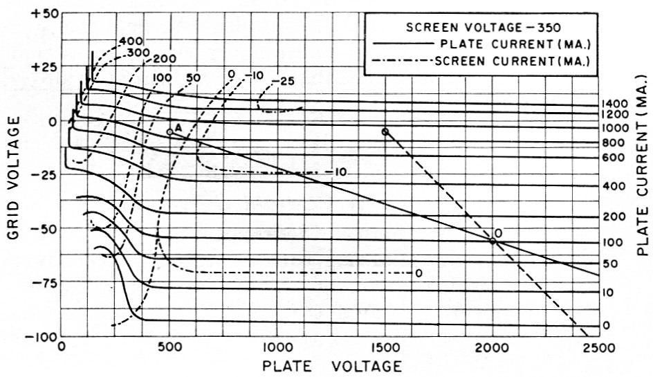
Fig. 1. Typical constant-current characteristics for the Eimac 4CX300A tetrode.
Inspection of Fig. 1 will reveal that the lines of constant plate current are nearly horizontal, whereas the constant-screen-current lines are tilted upward from left to right and are concentrated in the left-hand region of the plot. This is generally true for all tetrodes and accounts for the fact that the screen-current meter is tie most sensitive indicator of resonance. This important fact will be explained subsequently.
Let us plot a typical operating line(1) on our set of curves, as in Fig. 1. Point O (at -55 volt on the grid in this case) is the operating point at which the tube rests with zero r.f. grid drive. Straight line OA represents a tuned r.f. circuit load (a pure resistance at the operating frequency).(2) As 100 volt peak-to-peak grid drive is applied, the first positive half cycle can be represented by a point moving along the operating line from O to A and back to O again. During this half cycle, the grid-voltage swing from -55 volt up to -5 volt and back to -55 volt has caused the plate current to swing from the value at point 0 (100 mA) up to the value at point A (850 mA) and back to 100 mA again. At the same time, the plate voltage swings from 2000 volts down to 500 volt. The a.c. plate current is made up of all the instantaneous values intercepted by the point traveling along the operating line. The same is true of screen current. During the other 180 degrees of the driving cycle, our point merely travels from O down the slope through cutoff to a point opposite -105 volt on the grid-voltage scale and back to point O again along the operating line. Thus, the negative-going grid voltage swings the plate current down to cutoff (for a small portion of the cycle). Plate voltage continues on up to 3500 volt and back down again due to the fly-wheel action of the plate tank circuit.
Drive and tuning
Now that we can predict exactly what the screen and plate current will be for any instantaneous point during the grid-voltage cycle, let us ask some more probing questions. What happens when we cut our grid-driving voltage in half? The answer is simple. The length of our operating line is merely cut in half! The grid voltage swings to only one half the original peak-to-peak amplitude and the operating point O is still the center of the new operating line length. Now what happens if we detune the plate tank circuit? Detuning the plate circuit actually changes the plate load impedance. How does this appear on our set of curves? It tilts or rotates the operating line about the operating point O. As the load impedance is lowered (detuning from resonance), the operating line3 assumes a steeper angle (a zero-impedance load would be represented by a vertical operating line).
As "seen" by the tube, the act of tuning to resonance amounts to increasing the load impedance to a maximum value consistent with the degree ,f antenna loading selected. Thus, the operatin'g line will have minimum slope at resonance. Notice the angle at which our typical operating line in Fig. 1 cuts the constant-platecurrent lines. It's a small angle. As the plate tank circuit is tuned to a point out of resonance, the operating line might assume the position indicated by the dashed line(3) (lower impedance). Note that the angle between the dashed line and the''plate-current lines has not changed radically, and that our moving point will still intercept essentially the same plate-current values. This is precisely the reason that plate current in a tetrode is not a good indicator of resonance (very little dip). Look at the screen current. It consists of zero or even negative values in the out of resonance position. At resonance, though, it is positive.'Thus, a peak in screen current indicates resonance.
During the rotation of the operating line while tuning, its length actually changes, since it is confined vertically only by the constant peak-topeak amplitude of the grid-driving voltage (two imaginary horizontal lines, one at -5 volts and one at -105 volt). The length increases as resonance is approached and reaches a maximum at resonance. As the length increases, point A penetrates the heavy-screen-current region and the d.c. screen current reaches a sharp peak at resonance.
Loading
What happens if we change the antenna loading? This merely changes the plate-load impedance (still resistive). Again, the effect is to tilt the operating line about the operating point. As the load impedance is lowered (more coupling), the operating line assumes a steeper angle (such as the dashed line). It is easy to see that as loading increases, screen current decreases. Thus, screen current is also an indicator of loading. Screen current varies somewhat from tube-totube of a given type, but if each tube is loaded to the same value of screen current at resonance (with the same drive) power output differences will be small, and loading and linearity will be essentially the same.
D.C. meter readings
During the r.f. cycle, our point traverses the operating line and intercepts many different instantaneous values of screen current and plate current. The average of all these values is what the d.c. meter in the circuit reads. The fundamental frequency component of plate current is utilized in the plate circuit to produce output (except in a multiplier where use is made of a harmonic component of plate current). For a given operating line, both of these values can be calculated.(4) Suffice it to say that for Class AB1 operation, the d.c. meter reading is approximately one third the peak value of current at the top of the operating line, and the fundamental component of plate current is approximately one half the peak value.
Tune-up procedure
Contrary to somewhat popular opinion, a linear amplifier should never be loaded for maximum power output. Loading should be set to obtain a predetermined value of screen current under single-tone or inserted-carrier driving conditions. Ideally, loading should be set for minimum distortion - a rather difficult feat in practice. It is recommended that the amateur try to duplicate as nearly as possible a given set of data-sheet conditions as presented by the tube manufacturer. These typical operating conditions are usually given for peak-envelope operation (single-tone or inserted-carrier) and represent the maximum input on c.w. or the peak-envelope-power input (not meter peaks) on single sideband. After adjusting drive, tuning, and loading to duplicate a given set of conditions, the single tone (or carrier) is removed and the single-sideband audio gain is adjusted so that grid current is never drawn and the condition adjusted for above is never exceeded on peaks. The peak-to-average ratio of d.c. plate current (as read on a fluctuating meter) varies, with the individual voice, from about 2:1 to over 3:1. Thus it is normal on voice peaks for the plate-current meter to read no more than half the value of current obtained in the maximum static single-tone condition.
A straightforward tune-up procedure consists of the following steps:
- Insure that the tetrode amplifier is neutralized and free of parasitics.
- With recommended heater, plate, and screen voltages applied, adjust the d.c. grid bias to obtain the recommended zero-signal value of plate current. This value affects linearity and plate dissipation.
- Connect a suitable dummy load and set the loading control for rather heavy loading.
- With a single-tone source, gradually increase the drive from zero to a value that produces a significant though small change in screen current.
- Resonate the plate tank circuit by tuning for a peak (in the positive direction) in screen current.
- Resonate the grid tank circuit (if any) by watching for a peak in plate current.
- Now increase the drive until either the desired value of single-tone screen or plate current is reached (whichever is reached first).
- Without drawing grid current, adjust loading, plate-tank tuning, and drive level to duplicate as nearly as possible a given set of datasheet peak-envelope conditions. Remember that plate current increases with drive, whereas screen current peaks at resonance and decreases with heavier loading.
After matching a set of data-sheet conditions, the amplifier is ready to connect to an antenna. With a suitable antenna connected, it should be easy to repeat the operation obtained in Step 8 above by merely adjusting plate-tank tuning and loading with the same drive level as before. Now set up for voice single-sideband drive and adjust the audio gain for the highest level possible without drawing grid current on voice peaks or flat-topping (check this with a scope).
Reverse screen current
Most transmitting tetrodes employing oxide-coated cathodes exhibit negative screen current under certain conditions of operation. This is nothing to get alarmed about - it merely means that on the average, more electrons are leaving the screen than are being intercepted by the screen. This results because of secondary electron emission at the screen grid. Small values of negative screen current are not detrimental to tube operation and are quite normal for some tetrodes. Such values usually appear under heavily-loaded conditions or during the idling condition.
Large values of negative screen current are abnormal and should be avoided. Excessive secondary emission usually results in higher values of intermodulation distortion. This condition also prevents an accurate determination of screen dissipation.
Protection
Screen protection can take many forms. Before using a given circuit, it should be analyzed to insure that it satisfies the two basic criteria for screen protection. First, the circuit connected to the screen must be capable of maintaining the proper screen voltage in the presence of moderate negative d.c. screen current, or normal positive values of current. Second, the protective circuitry must not allow a condition of excessive screen current (positive or negative) to persist, since this causes excessive screen dissipation and resultant tube failure.
The first of these two criteria can be easily satisfied by the use of a bleeder resistance connected directly from the screen to ground, in combination with a suitable well-regulated power supply. The bleeder resistance should be made equal to the screen voltage divided by the largest negative d.c. screen current to be expected for the particular tube used. This eliminates any power-supply problems (soaring voltage) when "supplying" negative screen current.
Complete screen protection satisfying both criteria can be obtained by adding a screen-current overload relay to a bleeder and regulatedpower-supply combination. The overload relay will protect the screen against excessive currents, either positive or negative, and the regulated power supply will maintain the screen voltage at the proper value as the d.c. screen current varies. The bleeder resistance from screen to ground will not allow the screen voltage, in the presence of negative screen current, to rise above the proper value. This bleeder is good insurance, since even some regulated power supplies react in an undesirable manner when subjected to a negative-current load.
When using a screen-current overload relay, one can easily provide for manual resetting in the event of an overload. This feature allows time to consider why the overload occurred and prevents repeated successive overloads. Using an s.p.d.t. relay, merely connect the armature to the positive supply through the coil (with the usual pull-in-adjusting potentiometer shunting the coil). Connect the normally-closed contact to the screen through the screen-current meter and the normally-open contact through a resistor to ground.5 Adjust this resistor so that the current through it will hold the relay closed, once it has been tripped. First, of course, the pull-in shunt should be adjusted for pull-in at the value of screen-bleeder current, plus screen current, that produces maximum rated screen dissipation. Now, with this circuit it will be necessary to shut off the screen supply (or push a circuit-breaking series reset button) to reset the overload relay after an overload has occurred.
In contrast to the protective scheme outlined above, voltage-regulator tubes offer a simple and nearly foolproof method of screen-current protection. Their use will completely satisfy the first criterion and also the second criterion insofar as positive current overloads are concerned. Since excessive negative current is uncommon, one may elect to disregard protection against its occurrence. VR tubes then become an inexpensive and practical solution for the amateur.
The VR tube solution consists of an appropriate combination of VR tubes (to add up to the desired screen voltage) connected in series to ground and fed from a high-voltage source through an adjustable dropping resistance. The screen bypass capacitor from screen to ground and a screen-current meter from screen to the top of the VR-tube string complete the circuit. Adjust the dropping resistance to so that the VR string extinguishes at or slightly lower than the value of screen current that produces maximum rated screen dissipation. It.f. screen-current peaks will be supplied by the screen bypass capacitance and the VR tubes will "see" only the d.c. component. Now, excessive positive screen current will extinguish the VR tubes, lowering the screen voltage. The VR tubes will supply normal positive current values while maintaining screen voltage at the desired value. Negative currents will not change the voltage, but will merely increase the current flowing through the VR tubes.
Use a screen-current meter!
In conclusion, it should he obvious to the amateur that a screen-current meter is a vital necessity in modern transmitters employing tetrodes. By proper interpretation of screen-current readings, one can easily tune to resonance and properly load the tetrode amplifier. The plate-current meter is useful only as an indicator of drive level and average plate-input power (knowing the plate voltage). One more meter - for grid current - is useful but not absolutely necessary. A one-milliampere meter in the grid circuit will warn the operator by a slight kick when grid current is being drawn on voice peaks.
Notes
- This is different from the usual load line associated with audio calculations using plate characteristic curves.
- OA is actually only half the operating line length. The other half continues from O out beyond the right-hand edge of the chart for an equal distance and represents the effect of the negative half-cycle of grid driving voltage as it swings down to -105 volts and back to point O again. This half of the operating line is not important since the tube goes not "work" during the negative half cycle.
- The tank-circuit impedance would no longer appear resistive* the operating frequency, but would contain a reactive component. tinder these conditions, the operating line becomes an ellipse whose center is point O and whose major axis is represented by the dashed line.
- By the use of the Eimac Tube Performance Computor, Application Bulletin No. 5, which is based on the method presented by Chaffee in the Review of Scientific Instruments, October, 1936.
- See Evans, "Screen protection and more," QST, October, 1960. - Ed.
David D. Meacham, W6EMD.