A complete two-band station for the V.H.F. beginner 2 - The transmitters
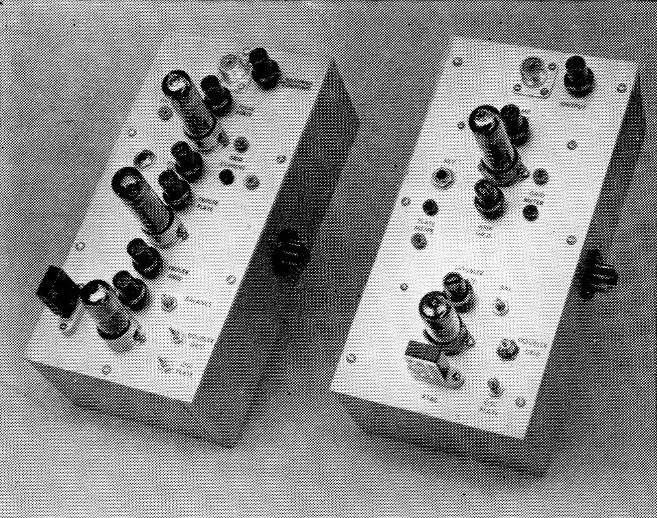
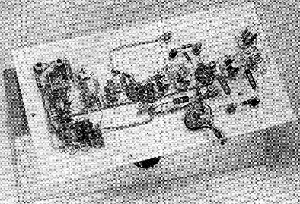
The r.f. units for 144 Mc (left) and 50 Mc are as much alike mechanically and electrically as possible. Shown here side by side, they have their crystal oscillators at the low end of the picture. Provision is made for measuring grid and plate current by plugging a meter into insulated tip jacks. The transmitters plug into the side of the modulator and power-supply chassis (to be described in a later issue), or they may be connected to it through 4-wire cables of suitable length.
You can build a transmitter for 50 or 144 Mc with fewer parts and simpler circuits than the ones shown here. You might even develop the same power output for a bit less money than we have spent. But simplicity and low cost can be delusions. We started with Vh.f. crystals, for example, and came up with a one-tube 6 meter rig and a two-tuber for 2. They were unstable, both as to warm-up drift and frequency shift under keying and modulation, so they were ruled out. The same tube lineup we show can be used with fewer tuned circuits, but it may radiate strong unwanted harmonics, and be something of a neighborhood nuisance.
These r.f. units were designed to be easy to build and adjust. They are stable in operation, and are relatively free of unwanted frequencies that could cause TVI. They scrimp on no essentials, and they have features that may save you money in the long run. Both employ crystals that are inexpensive and reliable. By shopping for surplus crystals you can afford enough of them to operate close to any desired frequency. Shifting from one spot to another is done with a minimum of retuning, thanks to a reserve of driving power all along the line. The oscillator circuit is readily adapted to Vf.o. control, should you want to go to it eventually. The transmitters can be keyed for c.w., and the signal will sound like a c.w. signal should, without the annoying yoops so often heard in Vh.f. c.w. work. With this equipment your signal will require no apologies, and you will have a fine base on which to expand to higher power later on.
The circuits
It will be seen that the transmitters are very similar. They are so much alike, in fact, that we did not repeat duplicate parts of the circuit in the diagram of the 144-Mc. model. The two transmitters will be described concurrently, and unless the text states otherwise, what is said will apply to both units. The crystal oscillator is the pentode section of a 6CX8 dual tube. The 6CX8 triode is a doubler stage. Crystals between 8000 and 8222 kc are used for the 2 meter band (8056 to 8166 kc for the Novice-Technician portion between 145 and 147 Mc) and 8334 to 9000 kc for the 50 Mc band Those between 8334 and 8350 kc should be used for c w. operation only, as they multiply into the first 100 kc of the 50 Mc band, which is set aside for that mode only. Appropriate crystals between 6000 and 6750 kc may also be used, as may 12 and 24 Mc crystals. The latter two are overtone types, and will not be as stable as those for 8 or 6 Mc.
The oscillator requires no adjustment other than moving the core in the plate coil, L1. This is tuned between 24 and 27 Mc, depending on the crystal frequency. The 6CX8 pentode triples the frequency for 8 Mc crystals and quadruples it for 6 Mc ones. Loosely coupled tuned circuits, L1 and L2, in the oscillator plate and doubler grid emphasize the desired harmonic and help to reject unwanted other frequencies that are developed in the oscillator.
Attenuation of unwanted frequencies is aided by the use of inductive coupling between the doubler plate circuit, CiL3, and the following grid circuit, C3L4. Note that here a single-ended stage is coupled to a push-pull one. The capacitor C3 is used to balance this circuit for coupling to L4. It places a capacitance similar to the plate-toground capacitance of the tube at the opposite end of La from the plate. Its adjustment is not critical.
The stage following the doubler looks the same in both schematic diagrams, but it is an amplifier for 50 Mc and a frequency tripler for 144 Mc. Its plate-screen circuit is modulated when the 50 Mc transmitter is used for voice work. In the 144 Mc model this stage triples from 48 to 144 Mc and drives a similar stage as an amplifier. Modulation is applied to the latter stage in 2 meter phone operation. Both tripler and amplifier are 6360 dual tetrodes. Power input to the amplifier runs about 15 watt on phone, but may be increased to 20 watt or more on c.w. The key is inserted in the amplifier cathode jack, A. Tuned antenna coupling conveys the transmitter output to a coaxial line to the antenna change-over relay, which is part of the modulator unit, to be described later. Tip jacks are provided for measuring tripler and amplifier grid current, and amplifier plate current.
Construction
The transmitters are built on aluminum plates that are screwed onto aluminum chassis 5 by 10 by 3 inch in size. Leads are brought to a plug mounted in the right side of the transmitter chassis, for plugging into the power socket on the left side of the modulator chassis. The transmitter and modulator units may also be operated apart by making up a suitable cable for connecting the two. Drilling templates for the transmitters are available on request from ARRL.(1)
It will be seen that various components come close to the edges of the plate on which the transmitter is built. To avoid possible damage when the units are mounted on or removed from the chassis, it is desirable to cutaches in the folded-over edges of the chassis to e plenty of clearance around these parts. This is particularly true of the output tuning capacitors, which are vulnerable in this respect.
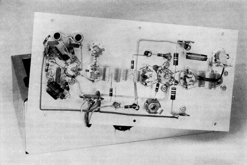
Bottom view of the 50 Mc transmitter. The crystal oscillator is at the left. The amplifier plate circuit and antenna loading control are at the right.
The transmitters are shown together in the top view, with the 144 Mc model at the left. The crystal oscillator and doubler are at the bottom of the picture for each, with the antenna jack and tuning capacitor at the opposite end. In the bottom views the oscillator tube and components are at the left end of the assembly. The oscillator plate and doubler grid coils appear in the upper left corner. These are % inch apart, center to center, in the 144 Mc transmitter, and 1 inch in that for 50 Mc. Smaller-diameter coils were used in the former, though similar ones could have been used in each. The coupling link between these coils is made of a single piece of insulated wire looped around one coil, the leads crossed over and then looped around the other coil and then the ends soldered together. The figure-8 loop is visible in both pictures.
The spacing between the inductively coupled coils elsewhere in the transmitters is given below the schematic diagrams. It will be seen that the doubler plate and tripler-amplifier grid coils, L3 and L4, are side by side, whereas the tripler plate and amplifier grid coils in the 144 Mc rig, L5 and L6, are mounted on the same axis.
Wiring of the transmitters is extremely simple. Use tie-point strips liberally for terminating power leads and mounting resistors and bypass capacitors. Shielded wire can be used for power leads, though it was not done in these units. Run power wiring flat against the plate. The ready-wound coil stock can be tapped most readily if the turn where the tap is to be made is pressed down toward the center of the coil with a small screwdriver. Connection to the tap is then made on the inside of the coil, using a small soldering iron. The coils are supported by their own leads, soldered to the tuning capacitors as directly as possible. Cutting of Miniductor stock was described in Part 1.
Adjustment and operation
The transmitters can be tested with any power supply that will deliver 200 to 300 volt d.c. at 100 mA, and 6.3 volt a.c. or d.c. at 2½ ampere. A single 1 mA meter can be used for all tests, if it is provided with a 1000 ohm series resistor and flexible leads with terminals, as shown at the lower left side of Fig. 3. (The s.w.r. bridge meter will be used this way in the complete station.) If the supply delivers more than about 200 volt, it would be well to connect a 5000 ohm 10 watt resistor in the supply lead temporarily, to keep the transmitter from drawing excessive current at the start of testing.
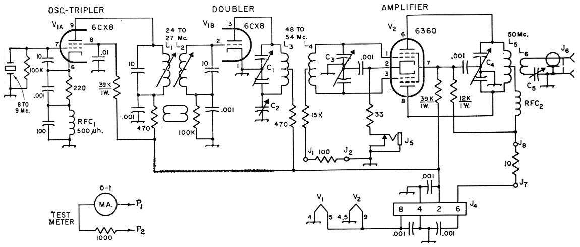
Fig. 3. Schematic diagram and parts information for the 50 Mc transmitter. Fixed 10 and 100 pF capacitors are mica; 0.01 and 0.001 µF are ceramic disk. Decimal values are in µF. Resistors are ½ watt unless specified; values in ohm. The oscillator and doubler stages of the 144 Mc transmitter are similar.
| C1,C3,C4 | 8 pF miniature butterfly variable (Johnson 160-208 or 9MB1 1). |
| C2 | 8.7 pF miniature variable (Johnson 160-104 or 9M11). |
| C5 | 50 pF miniature variable (Hammarlund MAPC50-B). |
| J1,J2,J7,J8 | Insulated tip jack. |
| J4 | 8 pin male chassis fitting (Amphenol 86-CP8). |
| J5 | Closed-circuit phone jack. |
| J6 | Coaxial output receptacle, SO-239. |
| L1,L2 | 3 µH (approx.) iron-slug coil (Miller 4404). Link L1 and L2 with 1 turn loops of insulated hookup F wire. |
| L3 | 10 turns No. 20 tinned, ¾ inch diam., 16 t.p.i., c.t. (B & W No. 3011). |
| L4 | 8 turns like L3. L3 and L4 are side by side, 1 inch apart center to center. |
| L5 | 11 turns like L3. |
| L6 | 1¾ turns insulated hookup wire around center of L5. |
| P1,P2 | Insulated tip plug. |
| RFC1 | 500 µH r.f. choke. |
| RFC2 | Single-layer Vh.f. r.f. choke, 4 to 7 µH 42 turns No. 26 enamel, close-wound on 9/32 inch dowel. |
We will test the oscillator and doubler first. Disconnect the screen resistors from both 6360 stages in the 144 Mc. transmitter, or from the amplifier in the 50 Mc. rig. This will keep these stages from drawing anything but grid current. Plug the test meter, with the 1000 ohm resistor in series, into Jl and J2. It will read as if its scale were 10 mA. (A reading of 0.4 will actually be 4 mA.) With the tubes already heated, apply plate voltage briefly, through Pin 2 of J4. If the first two stages are functioning there will be some grid current reading.
Using only short test periods at first, adjust the cores in L1 and L2, and the settings of C1 and C3, for maximum grid current. Now adjust C2 for maximum grid current. It will be seen that C1 and C2 interlock. Move first one and then the other until the combination is found that gives the highest grid current. This should be at least 1 mA in the tripler of the 144 Mc transmitter, and 2 mA for the 50 Mc amplifier, when a supply voltage of 250 is used, and it may be up to twice these values. If a dropping resistor was used in the power supply lead, it may now be removed, provided that the plate voltage does not rise to over 300.
And how do you read voltage? It's nice to have a voltmeter, but you can make your own. Remember Ohm and his famous Law? Connect a 1-megohm resistor in series with your 1-mA meter, with or without its 1000-ohm resistor, for the latter will make only a 0.1 per cent difference. Connect the negative side of the meter to the chassis, and the positive side (with the 1-megohm resistor in series) to the point where you want to measure voltage. You can now read voltage on the meter scale. A meter reading of 0.3 mA will mean 300 volts, 0.28 would be 280 volts, etc. It is desirable.to have a fairly accurate resistor for this purpose, if you want to read voltage to useful accuracy. A precision resistor will be a good investment here, but get one that is accurate to plus or minus 5 per cent, in any case. Some resistors may be as much as 20 per cent off, unless you specify otherwise.
50 Mc amplifier adjustment
The 50 Mc amplifier may now be adjusted, but first we need some kind of dummy (non-radiating) load. The best load is a bank of resistors that will total about 50 ohm and be able to dissipate at least 8 watts.(2) To use such a load properly requires some form of power output indicator, inserted in the line to the load. The s.w.r. bridge, to be described later, serves this purpose.
Lamps of various kinds can be used, but they are inferior loads. They do have one advantage, however: they give a rough visible indication of power output. Probably the best lamp load is made of 4 or 5 blue-bead pilot lamps (No. 44 or 46) connected in parallel. A 25 or 40 watt lamp may also be used, but it will be far from a 50 ohm load, and very misleading as to tuning of the final plate and loading circuits. If such a lamp is used, short out the loading capacitor, C5, temporarily.
With the two previous stages having been tuned for maximum amplifier grid current, reconnect the screen resistors. Modulation is not needed at this stage, so Pins 2 and 6 of J4 may be connected together initially. Plug the meter and 1000 ohm series resistor into J7 and J8, to measure amplifier plate current and apply voltage. The meter will now read as if it had a 100 mA scale. Adjust C4 quickly for minimum plate current, which should be about 50 to 80 mA, if a load is connected to J6. If the load is a lamp or bank of lamps, adjust C4 for maximum brilliance. With the pilot-lamp load C5 may now be adjusted for maximum brilliance. Retune C4 and C5 several times for greatest output. If a regular home light bulb is used for the load, short C5 temporarily and adjust C4 for maximum brilliance. Maximum output will occur at approximately minimum plate current, but there may not be exact coincidence, so C4 should be adjusted for the lowest plate current that gives maximum output.
The 6360 is so designed that there is no need for neutralization if the transmitter is properly designed and built, but a stability check should now be made. Plug the meter back into the grid-current jacks, turn on the transmitter, and briefly remove the crystal from its socket There should be no grid current with the crystal removed. The input to the amplifier will run excessively high under this test, so do it for a short check only.
Another test for stability is to observe the grid current and plate current simultaneously, while watching the output. A perfectly stable transmitter will show maximum grid current, minimum plate current and maximum output at a single setting of the plate capacitor. Some divergence from this ideal is permissible, if other indications given above are achieved.
144 Mc adjustment
Thus far we've been talking about the 50 Mc transmitter. Adjustment procedure is similar for the 144 Mc model, Fig. 4, except that there is a bit more to it. Proceed as above to the point where you have gotten grid current in the tripler stage. Now connect the screen resistor of the tripler and put the meter in tip jacks J2 and J3, to measure amplifier grid current. Apply voltage through pin 2, and tune C4 for maximum amplifier grid current. This should be at least 2 mA, but it may be as much as 5.
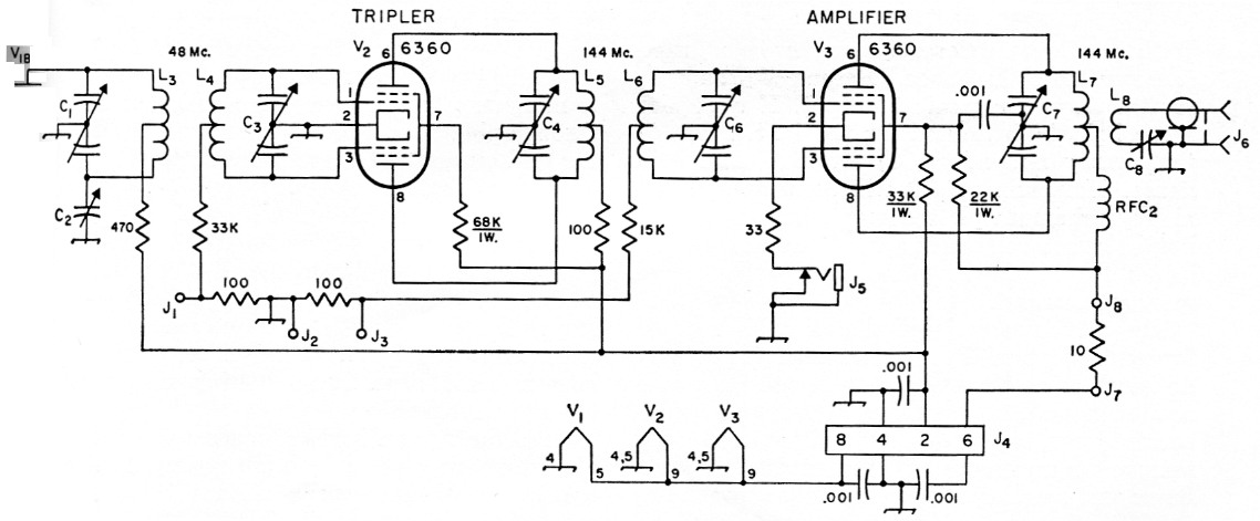
Fig. 4. Schematic diagram and parts information for the 144 Mc transmitter. Only the tripler and amplifier portions are shown, as the oscillator and doubler stages are similar to the 50 Mc unit. Components not listed below are identical to those of Fig. 3.
| C3,C6 | 5 pF miniature butterfly variable (Johnson 160-205 or 5MB11). |
| C4,C7 | 8 pF miniature butterfly variable (Johnson 160-208 or 9MB11). |
| C8 | 30 pF miniature variable (Johnson 160-130 or 30M8). |
| J3 | Insulated tip jack. |
| L1,L2 (in Fig. 3) | 4 µH (approx.) ¼ inch iron-slug coil (Miller 4504). Link with 1 turn insulated hookup wire; see photo and text. |
| L3 | 13¼ turns No. 24 tinned, ½ inch diam., 32 t.p.i., c.t. (B & W Miniductor 3004). |
| L4 | Same as L3, but 10¼ turns. Mount L3 and L4 7/8 inch apart, center to center. |
| L5 | 3¾ turns No. 20 tinned, ½ inch diam., 16 t.p.i. (B & W No. 3003). |
| L6 | 2¼ turns like L5. |
| L7 | 6 turns No. 18 tinned, 3/8 inch diam., 9/16 inch long, c.t. |
| L8 | 1 turn insulated hookup wire around center of L7. |
The 144 Mc transmitter is similar to that for 50 Mc , but it requires one more stage. Oscillator and doubler circuits are at the left end. Side-by-side coils in the doubler plate and tripler grid circuits come next. The tripler plate and amplifier grid coils, right center, are mounted on the same axis. The amplifier plate and loading circuits are at the far right.
Now plug the meter into J7 and J8 and apply plate voltage through Pins 2 and 6. Adjustment from here on is similar to the 50 Mc amplifier. Because of the drain imposed by the extra 6360 stage, the plate-supply voltage will be a bit lower with the 2 meter transmitter, a fact to keep in mind when figuring the input you will have to modulate.
Once the transmitters are made to work on a given frequency you may want to tune them so that shifting frequency can be done with a minimum of retuning. There is a surplus of grid drive with the tube lineups shown, so "stagger-tuning" is entirely practical. For instance, the 2 meter transmitter can be adjusted so that any frequency between 144 and 146 Mc can be used merely by inserting the proper crystal and retuning the final plate circuit. Plug the meter into the amplifier grid jacks, J2 and J3. With a crystal near 8000 kc in place, tune for maximum grid current. It will be more than you need. Now put in a crystal for some point near 146 Mc. The grid current will probably be 1 mA or less, and the output somewhat low, even when the final plate circuit is retuned. Adjust one of the core studs (either L1 or L2) upward slightly, and see if the grid current rises. Retune C1 or C3 slightly to further increase the grid current. Do the same with either C4 or C6. By judicious juggling it will be possible to get around 3 mA grid current on any frequency over a two-megacycle spread, simply by plugging in the proper crystal. You then merely retune C7 for the lowest plate current that will give maximum output, after changing the crystal. It is not necessary to readjust either C2 or C8 at any time, once they have been properly set. Adjustment procedure for spreading the coverage of the 50 Mc transmitter is similar, but simpler because of the lesser number of stages.
Ideal amplifier grid current in both transmitters is around 3 mA, though either will work well with down to about 1½ mA, or up to 4. More than 4 mA is likely to reduce the output, and either insufficient or excessive drive will affect the modulation adversely. The amount of grid drive for c.w. operation is much less critical, it being merely necessary to have enough to insure efficient operation. Even 1 mA will do. Keying the transmitters for c.w. work is done by plugging a key into the cathode jack, J5.
There will be more on transmitter and antenna adjustment in a later issue, when the modulator and s.w.r. bridge are described. Meanwhile, you may want to check operation of the various stages. Plate current may be measured in any stage, to be sure that it is running at safe input. Connect a 10 ohm resistor in series with the lower end of the 470 ohm isolating resistor in the plate circuit of the stage to be checked. Now, connect the 1 mA meter (with its 1000 ohm resistor in series) across the 10 ohm resistor. This will make the meter read as if it had a 100 mA, scale, just as when you plug into J7 and J8. Additional tip jacks shunted with 10 ohm resistors may, in fact, be permanently a part of the transmitters, though there will be little need to use them after the stages are once checked and found to be operating satisfactorily. The accompanying table shows typical voltages and currents measured in the original units.
| Stage | Plate voltage | Plate current | Screen voltage | Grid current |
|---|---|---|---|---|
| 144 Mc transmitter | ||||
| Osc. | 255 V | 12 mA | 140 V | - |
| Dblr. | 255 V | 10 mA | - | - |
| Tplr. | 255 V | 50 mA | 125 V | 1 mA |
| Amp. | 230 V | 70 mA | 170 V | 3 mA |
| 50 Mc transmitter | ||||
| Osc. | 270 V | 14 mA | 150 V | - |
| Dblr. | 270 V | 10 mA | - | - |
| Amp. | 250 V | 70 mA | 170 V | 3 mA |
Notes
- Templates for drilling the transmitter top plates, the tuner chassis, and the principal surfaces of the two converters are available, no charge, from ARRL. Send a stamped self-addressed envelope, and state which template you wish. Always give the ARRL publication, edition, page number and figure number, if any, in requesting templates.
- "V.H.F. dummy loads," QST March, 1960
Edward P. Tilton, W1HDQ.