Nuvistor preamplifiers for 50 and 144 Mc
Hopping up V.H.F. reception with simple R.F. amplifier stages.
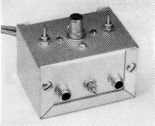
The Nuvistor preamplifier provides plenty of performance in a small package. The one shown is for 50 Mc. The 144-Mc. model is similar in external appearance.
Our evaluation of the Nuvistor in April QST(1) apparently stirred up quite a bit of interest and enthusiasm among v.h.f. men. Scores of letters tell of improvement in 50 and 144 Mc reception, all the way from "noticeable" to "spectacular" when 6CW4 preamplifiers were added to existing receivers. Also in the mail were requests for specific construction details for Nuvistor stages. So here's how to build 'em.
The preamplifiers are built in the smallest size Minibox, 2¾ by 2_1/8 by 1_5/8 inch in size, and the layouts are very similar. The 50 Mc amplifier uses slug-tuned coils, whereas the 144 Mc model has air-wound coils, except for the neutralizing winding, L2. In the 144 Mc amplifier, a variable capacitor tunes the input circuit, and no capacitor is used across the plate coil. Fixed 10 pF capacitors are used across both coils in the 50 Mc amplifier. The coupling in and out of the 50 Mc stage is inductive, whereas a tapped input circuit is used for 144 Mc. The latter is advisable in the interest of lowest possible noise figure at 144 Mc. This is less important at 50 Mc. The noise figure at the lower frequency probably will be lower than you can use, so a system which allows the use of ready-made coils was favored.
The Nuvistor socket is mounted in the center of the largest surface of the box in both amplifiers. On one side are the two phono jacks used for antenna and output terminals. Use better-quality coaxial fittings here if you like, but the low-cost jacks will do. The neutralizing winding is centered between the two jacks. The 50 Mc coils are mounted one inch either side of the Nuvistor socket. Similar points in the 144-Me. amplifier are for the ground lug at the bottom of L1, left, and the screw for holding the button bypass, C2, in place at the right. A 3 lug terminal strip is near the back wall of each amplifier, and wires for the heater and plate voltages are brought through a grommetted hole in the rear wall to this strip, heater on the left, plate voltage on the right.
Adjustment and operation
Because the preamplifier requires only 6.3 volt at 0.13 ampere, and around 50 to 70 volt at the plate, at a few milliamperes, power for it can be taken from the receiver or converter with which it is to be used, in most instances. The dropping resistor in the plate lead is shown as 10,000 ohm. This permits operation of the preamp on any available d.c. plate voltage between 150 and 250 volt. If the voltage is less than 150 at the source, the value of the dropping resistor can be lowered. The important point here is to keep the total input below the rated 1 watt, yet not so low as to have a bad effect on the noise figure.
The amplifier will work well down to about 40 volt or so, measured at the plate with a vacuum-tube voltmeter or high-resistance d.c. meter. Its overload characteristics and noise figure will be best if the input is allowed to run somewhere between ½ watt and rated maximum of 1 watt. The noise figure is so much better than is actually needed at 50 Mc, that you can't lose on this band, but at 144 Mc or higher frequencies, it may be well to check the operating conditions to see that the input does get up to around the ½ watt level, at least.
Adjustment is similar for the two amplifiers. Connect the amplifier to the converter or receiver by means of a length of coax between J2 and the receiver antenna terminal. With the cover on the preamplifier, and the antenna connected normally, but with only heater voltage on the Nuvistor, pick a strong signal in the part of the band where you want the preamplifier to work best. (Any frequency in the 144 Mc band will do, but the 50 Mc model may not be uniform across the entire band.) Tune the grid circuit approximately for maximum signal. Adjust the turn spacing or the core position in L3 also for maxi-man signal. Now adjust the core position in the eutralizing winding, L2, for minirr.um signal.
Now apply plate voltage and repeak the grid and plate circuits for maximum signal. This should be very close to the best that you can do, but optimum signal-to-noise ratio on weak signals may require more careful adjustment of the input circuit. The best way to do this is with a noise generator, but you can get results by adjusting the grid circuit for maximum change with respect to noise when a weak signal is tuned in. The position of the tap on L1 in the 144 Mc amplifier may require adjustment for absolute top performance, but any difference this might make will be difficult to observe unless you are set up to measure noise figure. The best noise figure will be obtained with L1 tuned slightly lower in frequency than the setting that gives maximum gain, though it is unlikely that this will be enough to make any practical difference in weak-signal reception on 50 Mc.
When you have gone through the above procedure completely it is well to repeat the process, as there is some interaction between the neutralizing setting and the tuning of the other circuits. Here, again, you may not be able to tell the difference except with the aid of a good noise generator.
What to expect
The gain of the Nuvistor preamplifier may be as much as 25 dB. This means that your S meter will read 3 to 5 S units higher than without the amplifier. How much this means in terms of improved reception depends on how bad your receiver was before. Don't be misled by the higher meter reading - what counts is whether or not you can copy the weak ones better now than before. The S meter is misleading at best, and just being able to give everyone "30 dB over S9" reports doesn't mean that you have done yourself any real good. Try ignoring the S meter. Tune in the weakest signal you can find. Now take off the amplifier, and reconnect the antenna to the receiver in the way you formerly used it. If you can still read the fellow, you had a good receiver to start with, so don't feel too badly. The way to read him better now is to put up a bigger or higher antenna, or move to a better location. Or give c.w. a try. That will enable you to work stations that are far below readability on voice, and it is the ultimate weak-signal medium.
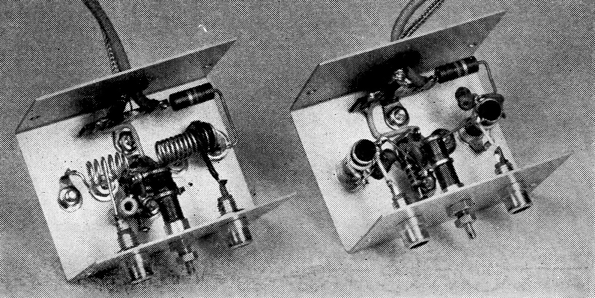
Interior view of the Nuvistor preamplifiers. The 144 Mc unit, at the left, uses air-wound grid and plate coils. Slug-tuned coils are used in the 50 Mc model.
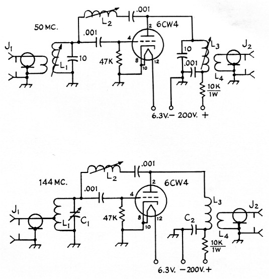
Fig. 1. Nuvistor preamplifiers for 50 and 144 Mc. Decimal values of capacitance are in µF; others are in pF. Except as listed below, capacitors are ceramic. Resistors are ½ watt composition except as indicated.
| C1 | 1-7.5 pF tubular (Centralab 829-7). |
| C2 | 1 nF button mica (Centralab ZA-102). |
| J1,J2 | Phono connector. |
| L1 | 50 Mc; Adjustable, 0.6-1.0 µH, iron-slug tuned (Miller 20A827RB1), with 3 turn antenna coil wound at ground end. 144 Mc; 6½ turns No. 18, inside diameter ¼ inch, length 5/8 inch, tapped 2½ turns from ground end. |
| L2 | 50 Mc; Adjustable, 5-10 µH, iron-slug tuned (Miller 20A826RB1). 144 Mc: Adjustable, 0.6-10 µH, iron-slug tuned (Miller 20A827RB1). |
| L3 | 50 Mc: Same as 50 Mc L1, with 3-turn output link. 144 Mc: 11 turns No. 18, inside diameter ¼ inch, length app. ¾ inch, adjusted as required (see text). |
Notes
- "An evaluation of the nuvistor," QST, April, 1961, p. 33.
Edward P. Tilton, W1HDQ.