High-power zero-bias grounded-grid linear
A 1 kW amplifier using the new 3-400Z triode.
The 811-A has long been popular in linear amplifiers because of the simplicity that results when neither screen nor bias supply is required. This feature has been projected in the new higher-power Eimac 3-400Z zero-bias triode around which this compact and clean-looking amplifier is built. The tube is rated at 1 kW p.e.p. input, and is designed especially for grounded-grid operation without neutralization.
The "ideal" linear amplifier package would contain no more than a tube, a filament transformer, a plate supply, and a tuned circuit. It would be simple to build and cost but a few pennies. Unfortunately, such a perfect device does not yet exist, and is not foreseeable in the near future. On the contrary, the customary linear amplifier has come to be an object of astounding complexity, requiring grid-bias supplies, regulated screen supplies, power-dissipating grid resistors and other awesome and complicated devices that add to the cost and weight of the linear but often do nothing to make the signal louder or clearer at the receiver. Indeed, some linear amplifier designs have been almost lost in the maze and complexity of expensive regulated power supplies required to make the beast "tick"
A large quantity of auxiliary equipment can be swept aside and junked if a zero-bias tube is employed in a simple grounded-grid configuration, such as shown in Fig. 1. Various types of transmitting tubes (originally designed for grid-driven service) such as the 813, 811-A, and 4-400A have been used with success as "zero-bias" grounded-grid amplifiers, but no true zero-bias triode of large power capability has been at hand for this class of service. The amplifier described in this article is designed around the new Eimac 3-400Z, a member of a family of zero-bias triode tubes now available to the amateur. Typical operating values are shown in the table on the next page.
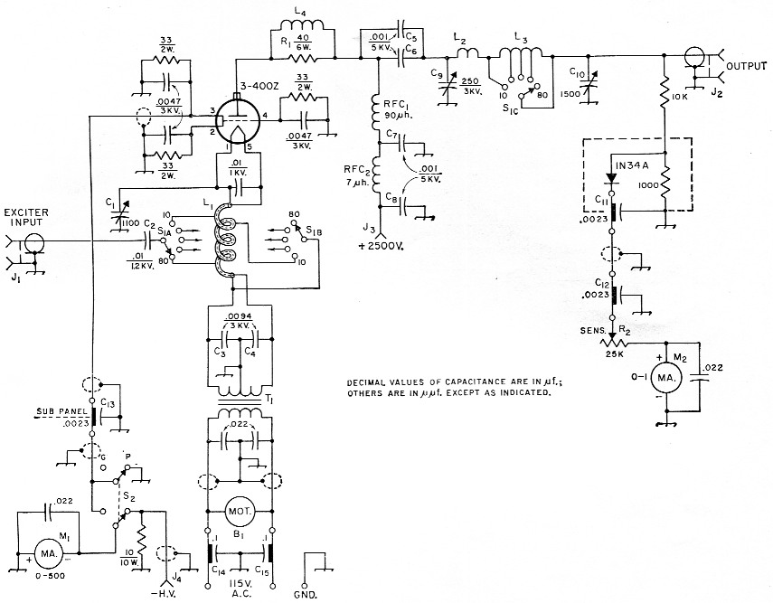
Fig. 1. Circuit of the high-power grounded-grid linear. Capacitors not listed below are disk ceramic. Resistances are in ohms and resistors are' Y2 watt unless indicated otherwise.
| B1 | 15 cu. ft./min. blower (Fasco Industries* No. 50745-IN). |
| C1 | 3 section broadcast-replacement variable, 365 pF per section, sections in parallel (Miller 2113). |
| C2 | Transmitting mica. |
| C3,C4 | Two 4n7 3000 volt disk ceramic units in parallel. |
| C5,C6,C7,C8 | Doorknob-type ceramic (Centralab 858S1000). |
| C9 | Transmitting variable, 0.075 inch plate spacing (Johnson 250E30/154-9). |
| C10 | 4 section broadcast-replacement variable, 365 pF per section, sections in parallel (Miller 2104). |
| C11,C12,C13 | Feed-through type capacitor (Centralab FT-2300). |
| C14,C15 | 600 volt 20 ampere feed-through capacitor (Sprague 80P3). |
| J1,J2 | Chassis-mounting coaxial receptacle (S0-239 or UG-58A/U). |
| J3,J4 | High-voltage connector (Millen 37001). |
| L1 | Coaxial winding-see text. |
| L2 | 6 turns 3/16-inch copper tubing, 1_3/8 inch i.d., length 4 inch. |
| L3 | Approx. 10 µH, tapped at 5 µH, 2.5 µH, and 1.5 µH. (part of modified B & W model 851 coil assembly - see text). |
| L4 | 4 turns No. 12, 3A-inch diam., 1 inch long. |
| M1 | 2 inch d.c. milliammeter, 0-500 mA scale. |
| M2 | 2-inch d.c. milliammeter, 0-1 mA scale. |
| R1 | Three 120 ohm 2 watt composition resistors in parallel. |
| R2 | Linear-taper control. |
| RFC1 | 90 µH 500 mA r.f. choke-175 turns No. 26, 4_3/8 inch long on ¾ inch ceramic form (B & W 800). |
| RFC2 | V.h.f. choke (Ohmite Z-50). |
| S1A-B | l section 2 pole 5 position ceramic rotary switch, 30 degree indexing (Centralab P-122 index assembly with one type RR wafer). |
| S1C | Single pole 5 position rotary switch (part of L3 assembly). |
| S2 | 1 section 2 pole 2 position ceramic rotary switch (Centralab PA-1003). |
| T1 | Filament transformer: 5 V, 13 A (Triad F9A). |
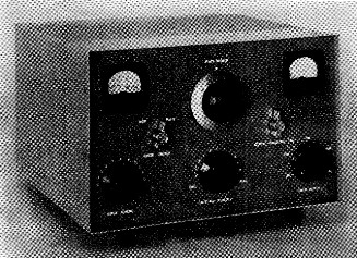
Clean and simple! This compact kilowatt grounded-grid amplifier in its TVI-suppressing cabinet makes an ideal companion for the current crop of space-saving desk-top exciter units. On either side of the plate tank tuning control are the plate/grid milliammeter with its switch (left), and the output indicator with its sensitivity control. Along the lower portion of the panel, from left to right, are controls for input tuning, antenna loading, and the band switch.
The 3-400Z zero-bias tube
The new 3-400Z tube is a high-a triode having a plate dissipation of 400 watt. It is rated to 1 kilowatt d.c. input for s.s.b. linear-amplifier service, as shown in the table of typical operating conditions. Within the maximum plate-voltage rating of 3000 volt, the 3-400Z has the very desirable characteristic of having need for neither grid bias nor screen power supply. Oldtimers will remember with nostalgia the ancient 46 tube. (Remember the pre-war 160 meter transmitter using a flock of these bottles?) When excitation was removed from the 46, it would simply relax and stop working. The 3-400Z will do this trick too. Used in a grounded grid circuit, no neutralization is required.
The seated height of the 3-400Z is only 4½ inch to the top of the plate radiator cap, making it extremely attractive for the new modern concept of linear-amplifier design. Because of the small tube size, and because no one has yet been able to miniaturize a watt, it is necessary to cool the tube seals, envelope, and plate lead with an auxiliary blower.
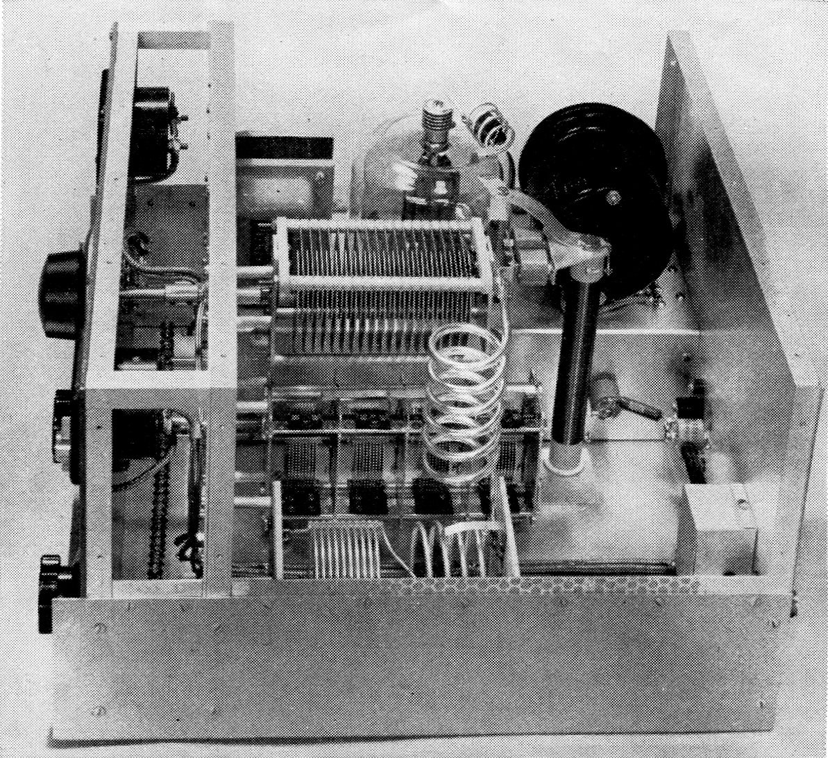
End view of the amplifier chassis. The plate tuning capacitor is supported from the sub-panel on three 1¾ inch metal pillars. It is centered 3 inches below the top of the panel. Below the plate capacitor and on the some center line is the loading capacitor with sections connected in parallel with copper strap. On the rear of this capacitor is mounted a small aluminum angle plate which supports the plate-circuit r.f. choke. On one rear stator terminal of the plate tuning capacitor is placed a bracket which supports the two plate-blocking capacitors C5 and C6. On the opposite stator terminal is a small bracket holding a 1 inch ceramic insulator. This supports the plate strap and one end of the parasitic suppressor. A third bracket connects the top terminal of the r.f. choke to the blocking capacitors. The small aluminum box at lower right contains the diode and associated circuitry of the r.f. output voltmeter. The two plate bypass capacitors C7 and C8 may be seen to the right of the plate choke, with the v.h.f. choke tied between. The plate tank-coil assembly is in the foreground.
Elimination of the bias and screen supplies allows a large saving in cash normally spent for these items, and also saves the builder the labor (and skinned knuckles) required to drill the holes, mount the parts, and do the necessary wiring on these electronic nuisances. A large bonus in the form of simplicity and low cost accrues to the user of a zero-bias tube!
The amplifier circuit
The 3-400Z grounded-grid amplifier shown in the photographs is designed for an input of 1 kilowatt p.e.p. sideband, or 1 kilowatt c.w. operation. In addition, it may be run as an a.m. linear amplifier at an input level of 600 watt (carrier output about 200 watt). Band-switching circuits are ganged, and cover the amateur bands from 3.5 to 29.7 Mc with generous overlaps. A pi-network output circuit is used. The order of tank capacitance is large to enhance a high degree of linearity. Since it is necessary to monitor the output level of any linear stage, a simple semiconductor voltmeter is incorporated in the output portion of the network. The voltmeter range is variable, since absolute readings are not necessary.
| General Characteristics | |
|---|---|
| Filament | 5.0 volt at 14.5 ampere |
| Interelectrode capacitances: Grid-filament: 7.4 pF Grid-plate: 4.1 pF Plate-filament: 0.07 pF | |
| Typical Operation | |
| 2500 volts plate potential, grounded-grid circuitry | |
| Zero-signal plate current | 75 mA* |
| Single-tone d.c. plate current | 400 mA |
| Single-tone d.c. grid current | 140 mA |
| Two-tone d.c. plate current | 275 mA |
| Two-tone d.c. grid current | 82 mA |
| P.e.p. input | 1000 watt |
| P.e.p. output | 560 watt** |
| Resonant load impedance | 3450 ohm |
| Intermodulation products | -35 dB or more below p.e.p. signal level |
| Driving power (approx.) | 32 watt, p.e.p. |
| * Approximate value. ** Includes circuit losses. | |
Proper operation of the amplifier may be established by maintaining a given ratio between grid and plate currents. The grounded grid, therefore, is "ungrounded" sufficiently to permit insertion of a simple metering circuit. If this is done properly, the stability and operation of the amplifier will remain unchanged. To achieve this, each of the three grid pins of the 3-400Z socket is grounded by a low-impedance resistor-capacitor combination. The resistors are shunted across the milliammeter, but have a value sufficiently high so as not to disturb the calibration of the meter to any great degree. High-voltage capacitor units are used here to obtain the required r.f. current-carrying ability.
Plate current is measured in the negative lead of the power supply, rather than in the filament return circuit, since the latter carries a combination of grid and plate currents. The negative side of the power supply is above ground by the voltage drop across a 50 ohm resistor, so it is necessary to "float" the power supply above chassis potential as shown in Fig. 2. The 10-ohm 10-watt resistor at J4 is included to provide a connection to the chassis should a conventional power supply (negative grounded to chassis) be used with its negative terminal connected to J4. In such a case, there would otherwise be no negative high-voltage connection to the amplifier with the meter switched to read grid current. On the other hand, connecting a conventional supply to the amplifier ground terminal would short out the meter in the plate-current position.
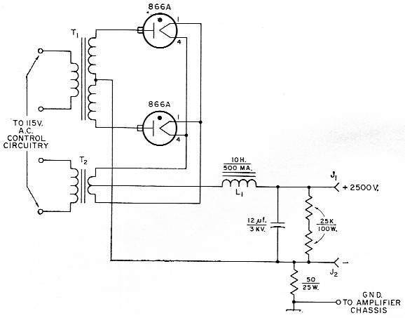
Fig. 2. Circuit of the power supply used with the 3-400Z amplifier. Resistances are in ohm.
| J1,J2 | High-voltage connector (Millen 37001). |
| L1 | 10 H, 500 mA filter choke (Triad C-22A or similar). |
| T1 | Plate transformer: 2900-0-2900 volt r.m.s., 375 mA d.c. (Stancor P-8034 or similar). |
| T2 | Filament transformer: 2.5 V, 10 A, 10 kV insulation. |
The driving impedance of the 3-400Z is a nominal 122 ohms. Since this figure varies widely over the operating cycle, a high-C tuned cathode circuit, C1L1, is employed to stabilize the load impedance as seen by the exciter. Filament voltage is applied to the tube via the coil of this circuit which is in the form of a coaxial winding having two sets of taps. One set of taps (Sin) is for establishing resonance in the various bands. Excitation is fed to the second set (Slit). The latter is set for minimum standing-wave ratio on the coaxial line from the exciter (50 ohms in this case). The usual driving difficulties experienced with grounded-grid amplifiers are entirely absent, and no coupling problems have been found in switching from band to band. Increased power output, reduced intermodulation distortion, and ease of drive are gained when a tuned cathode circuit is used in preference to the old-fashioned untuned r.f. choke input circuit.(1)
Construction of the tuned cathode circuit
The tuned cathode circuit is built as a discrete subassembly. The unit consists of the coaxial coil L1, the tuning capacitor C1, the coupling capacitor C2, bypass capacitors C3 and C4, and band switch sections S1A and S1B. The coaxial coil is wound from a 61 inch length of standard 3/16 inch soft copper tubing, available at auto-parts houses, refrigerator-repair departments, and large hardware stores. Before the coil is wound, a length of No. 12 Formvar-insulated copper wire is passed through the tubing, leaving about three inches protruding from each end. Be sure you sand the ends of the tubing to a smooth, rounded edge to prevent marring or scraping the insulation of the wire during this operation. Wire with enamel insulation should not be used, since enamel is too soft and may be easily damaged. Next, the coil is wound around a 1_5/8 inch form (a section of water pipe may be used), making a coil of approximately 10½ turns.
The copper-tubing coil has two taps for each band. The shorting tap (S1B) selects the proper tuning inductance for the band in use, while the other tap (S1A), placed slightly higher on the coil, is for coupling to the driver, as explained earlier. Counting from the top end of the coil (filament end), the 10 meter band tap is at 1½ turns with the excitation tap at 1 turn; the 15 meter tap is at 2½ turns and the excitation tap at 1½ turns; on 20 meter, the band tap is at 3½ turns and the excitation tap at 1½ turns (same as for 15 meter). On 40, the band tap is at 6½ turns, and the excitation tap at 3 turns. On 80 meter, the full coil is used with the excitation tap at 4½ turns.
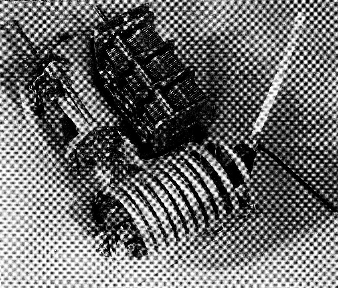
The high-C cathode tank circuit is made up as a separate subassembly. Band-switching leads ore of copper strap. Enameled wire is used for the excitation taps. The two terminals at the left-hand end of the coil-supporting strip are for filament input connections. Output connections to the tube socket are the loose strap and inner conductor to the right. This strop also makes the connection to the stator of the tuning capacitor. The fixed capacitor above the switch is the input coupling capacitor C2.
Soft copper strap ¼ inch wide is used for the band-switch leads and the 50 ohm driving points are tapped with No. 18 enameled wire. All taps are soldered to the copper tubing.
The completed coil is mounted on a piece of ¼ inch bakelite or phenolic sheet measuring 4 by 1_5/8 inch. The turns at the high-frequency (filament) end are spread as shown in the photo. The sheet is drilled and tapped to mount vertically on small ceramic standoff insulators bolted to the subassembly chassis. The chassis measures 6 by 4 inch, with a 2_3/8 inch lip on the front end.
When mounting the band switch, keep in mind that the plate inductor and the cathode inductor will be switched simultaneously by means of a chain and sprocket drive. Therefore, the cathode-coil switch must have the 80-meter setting fall in the full clockwise position corresponding to the tap sequence of the B & W coil unit used in the output circuit.
The capacitor C2, in series with the exciter input, carries the full excitation current and must be a transmitting-type mica unit. Filament capacitors C3 and C4 are paralleled ceramic units chosen to conserve space and yet provide sufficient capacitance to insure that the secondary of transformer T1 is at r.f. ground potential. These capacitors are mounted directly at the "cold" terminals of the coaxial filament coil. The plate-cathode r.f. return circuit is via the cathode tuned circuit. The lead from the stator terminals of C1 to the filament circuit and the coaxial coil is made of ut-inch copper strap.
The series input capacitor C2 is wired directly to the arm of the band switch with copper strap. The center conductor of the coaxial line from the exciter input receptacle is soldered to the coupling-capacitor terminal and the shield is grounded directly to the frame of C1. The impedance of this tuned circuit is extremely low, and care must be taken in the design and assembly to make sure that the impedance is in the tuned circuit, and not in the various interconnecting leads and switches.
Shielding enclosure
This little powerhouse measures only 8¾ inch high, 14 inch wide, and 15 inches deep - small enough to sit on the desk beside your sideband exciter or receiver. Construction is unique in that no chassis is used; the cabinet serves as the chassis. The TVI-suppressing enclosure is fabricated from 0.063 inch aluminum sheet and ½ inch aluminum angle stock. The front panel is cut from 1/8 inch dural and measures 8¾ inch high by 14 inch wide. The subpanel and rear panel are of the thinner aluminum cut to the same dimensions. All three pieces are framed with the corner stock as shown in the illustrations. Spacing between the panel and the subpanel is 2½ inch, the two being joined by four corner posts made of ½ inch-square aluminum stock.
The bottom of the enclosure is formed in the shape of a U, wrapping around the bottom and part way up the sides of the unit. This piece measures 14 inches wide and 15 inches deep. The sides turn up 3_5/8 inch. The forward edge extends ½ inch in front of the main panel. The top edges of the sides are backed up by strips of aluminum which serve as a means for fastening down the top cover and sealing the seam between the upper and lower cabinet sections.
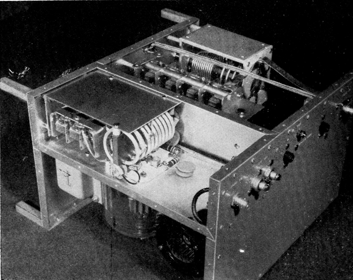
Bottom view of the 3-400Z grounded-grid amplifier, showing the mounting of the filament transformer, tube and blower on the L-shaped chassis. The cathode-tank sbbassembly above is mounted on the subpanel with spacers. The tube socket is oriented with the filament terminals toward the outer edge of the chassis to permit short connections to the near end of the coaxial coil. One of the three resistor-capacitor grid terminations can be seen at the right-hand side of the socket. (The two units in parallel are each half of the required capacitance and were used because they were on hand.) Along the rear are the r.f. input connector, the feed-through capacitors used as a.c.-input terminals, positive high-voltage connector, ground stud, negative high-voltage terminal (separate from ground) and the r.f. output connector. The output pi-network coil assembly and output capacitor ore in the background.
The top cover is also U-shaped, and is made of perforated aluminum to allow the exhaust air to escape from the main compartment. The cover measures 14 inches wide, 15 inches deep, and 5_1/8 inch high. The top and bottom pieces are attached to the frame by means of sheet-metal screws.
The input circuit of the amplifier is contained within an L-shaped box, as shown in the under-chassis photograph. The compartment is approximately 12 inches deep (this depth is determined by the finished dimension between the subpanel and the rear panel) and 3¾ inch high. It has two ½ inch lips, one along the side and the other along the bottom. Together with the bottom cover and the panels, it makes an r.f.-tight and airtight compartment for the cathode input circuit and blower, respectively.
The plate-circuit components require no chassis. The two pi-network capacitors are mounted to the subpanel by means of 6-32 screws and spacers. The plate-coil assembly is affixed in a similar fashion as shown in the bottom view.
Component layout and assembly
General component placement may be seen from the photographs. The panel meters are isolated from the r.f. circuits by virtue of the subpanel. The plate band switch and the cathode-circuit switch are ganged for ease of operation. In the meter area is also located the chain drive for the cathode band switch, as shown in detail in one of the photos. A 2-to-1 reduction drive ratio is needed, since the plate-inductor unit has 60-degree indexing, while the cathode switch has 30-degree indexing.
The filament transformer is placed at the front of the cathode-circuit box. Although slightly under-rated for the job, this unit has operated for hours with no evidence of overheating. The tube socket and chimney are centered on the box, 5½ inch behind the subpanel, and the remaining space is occupied by the centrifugal blower and motor. A Johnson ceramic socket was used for the tube, but the new Eimac SK-410 air socket and SK-416 chimney are recommended as an inexpensive substitute.
The band-switching plate-inductor assembly is at the opposite side of the main compartment. The unit is rated at 500 watt input. However, it was disassembled, silver-plated, and modified for one kilowatt sideband and c.w. operation. A new 10 meter section was wound, and the taps were altered to provide the proper L/C ratio for optimum amplifier linearity. First, turns are removed from the small-wire end of the coil until a total of 11½ turns remain in this section of the coil. The 40 meter tap is placed at 7½ turns from the antenna end of this section, and the 20 meter tap at the junction of the two coil sections. The 15 meter tap is on the large-wire section, 1½ turns from the 20 meter tap, leaving 2¾ turns at this end of the coil. A new coil was wound to replace the original 10 meter section. This consists of 6 turns of 3/16 inch copper tubing, 1_3/8 inch inside diameter, with a coil length of 4 inch. The new coil was mounted as shown in the side-view photo.
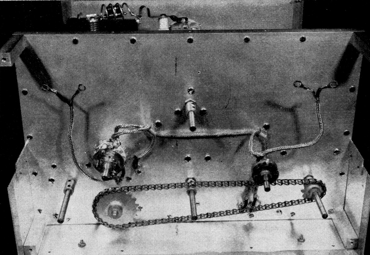
Removing the front panel reveals the chain-sprocket system which gangs the input and output band switches. Sprockets and chain are made by perfection Gear Co. (American Stock Gear Division, 152nd St. and Vincennes Ave., Harvey, III.) The small sprocket to the right (plate switch) is 1.125 inches in diameter, has 10 teeth and is designated as No. C-10. The larger one (cathode switch) is 2.030 inches in diameter, has 20 teeth and is designated as No. C-20. The chain designation is No. 18/42. About 2 feet are required. Ddngling on their leads are the meter switch (left) and the output-indicator sensitivity control. This view also shows the four square corner posts which space the panel from the subpanel.
Amplifier wiring
Shielded wire is employed for all low-voltage circuits and small feed-through capacitors pass the leads from the amplifier compartment into the meter compartment. Coaxial capacitors are employed as 115 volt a.c. terminals on the rear apron of the chassis. Silver-plated, ½ inch copper strap is used for the output wiring of the pi-network circuit. The four stator sections of the output capacitor of the network are paralleled by a short length of strap. Ail wiring is short and direct.
Testing the amplifier
The amplifier is entirely free from unwanted regeneration or parasitics, and operation is simple and straightforward. It is designed to operate with a 2500 volt, 400 mA power supply of good regulation. Fig. 2 shows the circuit of the power supply used with the amplifier.
Preliminary adjustments should be made at reduced plate voltage and with a minimum value of excitation. Excitation should never be applied without plate voltage. Once resonance is established, the tube should be loaded up to a plate current of approximately 400 mA. The grid current at this particular operating point should be about 140 mA. The ratio of about 3 plate milli amperes to 1 grid milliampere should be maintained for all operating conditions. If the grid current is excessive, it indicates that the plate-circuit loading is too light. Low grid current indicates that plate loading is too heavy. As a final check, it should be observed that the output of the stage (as observed on the output voltmeter) should increase in direct proportion to the excitation level. Finally, to achieve a condition of maximum linearity, the plate output circuit should be overcoupled (by decreasing the value of the pi-network output capacitor) until power output drops about 3 per cent. With a two-tone test signal, the maximum-signal plate current read on the meter should be 275 mA, and the grid current about 80 mA. With an average voice, plate current as read on the meter should kick up to about 180 or 200 milliampere, with grid current peaks of about 60 to 70 milliamperes. P.e.p. input under these conditions will be one kilowatt, and all spurious distortion products will be reduced better than -35 dB below peak-signal level. Under proper operating conditions, signal-to-distortion ratios better than -42 dB with a two-tone test signal have been achieved with this tube in this circuit. Distortion ratios of this order can be obtained with conventional amateur tubes only by employing feedback circuits.
The cost of all parts, including the tube, air socket, and chimney, is under two hundred dollars. Amateurs owning a good junk box, or who are "surplus hounds," can cut this cost figure considerably. Considered both on a watts-perdollar basis, and on a linearity basis, this little powerhouse is hard to beat for maximum performance!
Notes
- Orr, Rinaudo and Sutherland, "The grounded-grid linear amplifier," QST, August, 1961, p. 16.
Harold C. Barber, W6GQK
Robert I. Sutherland,W6UOV.