A complete two-band station for the V.H.F. beginner 4 - Crystal-controlled converters for 50 and 144 Mc
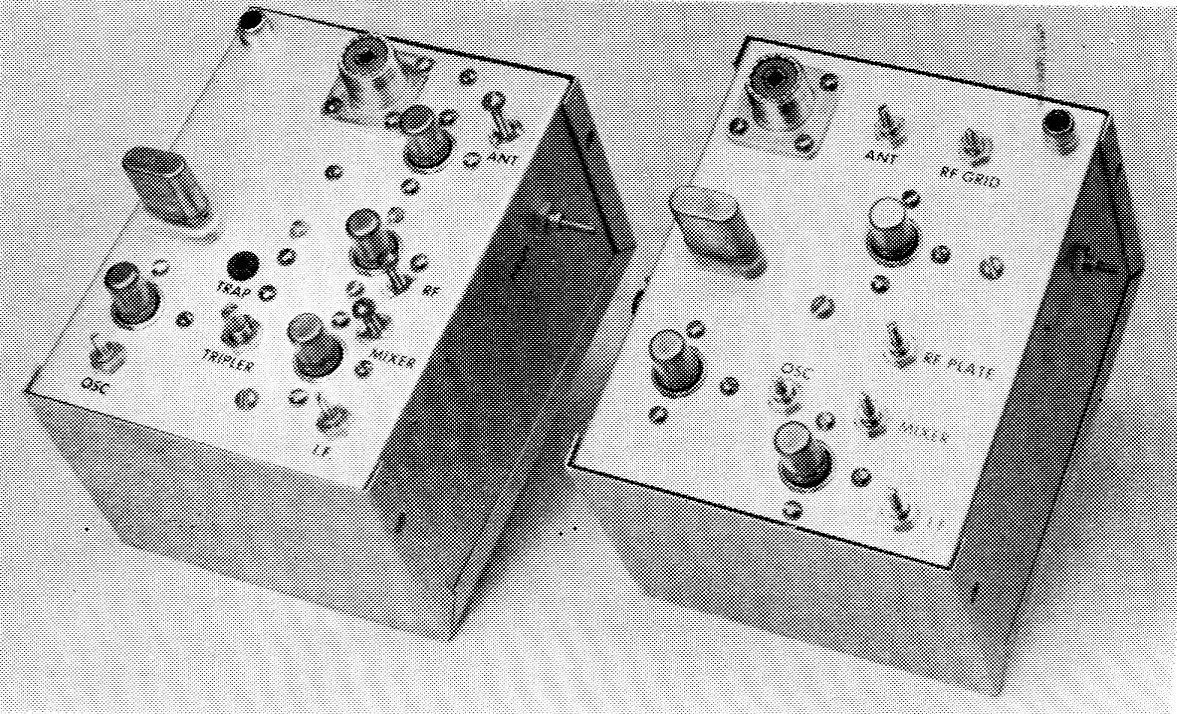
The 50 and 144 Mc converters are built in standard aluminum boxes, and fitted with plugs that line up with the power connectors in the tuner of Part I or the power unit of Part Ill. The 50-Mc. converter is at the right.
Thus far, we have described a simple tuner that will enable the v.h.f. newcomer to get started without a communications receiver, two transmitter r.f. assemblies, a modulator and power supply, and a standing-wave bridge. This final article of the series presents easy-to-build converters that are capable of exceptional v.h.f. performance. They work nicely with the tuner of Part I, and when the builder can afford the step to a good communications receiver, these converters will give him 50- and 144-Mc. reception that will equal almost anything that money can buy.
Noise figure and signal-to-noise ratio
First, let's talk about v.h.f. reception generally. The above expressions describing receiver performance are often confused. Noise figure is a mathematical statement of the degree to which a receiver is less than perfect in the amount of noise generated within it. This quality is independent of receiver bandwidth. Signal-to-noise ratio is a measure of the receiver's ability to respond to weak signals. It is directly related to receiver selectivity, as well as to noise figure. Thus, for optimum v.h.f. reception we need both low noise figure and high selectivity. These converters will give noise figures as low as can be obtained with relatively simple circuits at reasonable cost, but to achieve the best possible signal-to-noise ratio with them requires the highest selectivity that is usable for the mode of operation involved. Our simple tuner is deficient in this respect, obviously. It will give you a good start at low cost, but a good communications receiver that tunes 14 to 18 Mc will be necessary before you get the full benefit of the fine performance of these converters.
We use a converter to change the very high signal frequency to a lower frequency, where amplification can be done more effectively. This is also done in communications receivers, where a 14 Mc signal, for example, is converted to 455 kc or lower frequency, wheife most of the amplification takes place. Because few communications receivers cover the 50 Mc band and none cover the 144 Mc band, we need converters to extend the frequency range of the receivers used on lower amateur bands. Frequency conversion is accomplished by feeding in r.f. energy that will beat with the incoming signal in a mixer stage. The output of the mixer is either the sum or the difference of the signal and injection frequencies. Our 50 Mc converter has a 36 Mc crystal oscillator which beats with the signals in the range between 50 and 54 Mc, giving an intermediate frequency (i.f.) of 14 to 18 Mc. Amplification and detection can take place at this frequency, as in our simple tuner of Part 1, or the i.f. output can be fed into a communications receiver capable of tuning 14 to 18 Mc.
In most v.h.f. converters there are one or more r.f. amplifier stages that work at the signal frequency. These are the principal source of the receiving system's sensitivity, as they determine the noise figure of the entire system if they are working properly.
One more basic point before we get to the converter construction. At 50 Mc, noise coming in on the antenna is a limiting factor in receiving ability, even in the quietest locations. Such "antenna noise" is much lower at 144 Mc. This is one reason why we have two tubes in the r.f. amplifier of the 144 Mc converter and only one in the 50 Mc model. The latter has more sensitivity than you ever will be able to use, even with a single amplifier stage. The 144 Mc converter with its two stages just about reaches the point where antenna noise becomes a limiting factor in weak-signal reception.
Both converters use a new type of miniature tube called the Nuvistor, capable of high-gain low-noise amplification in the v.h.f. range. The 6CW4 Nuvistor is also well suited for, use in the other stages of the converter, and it is inexpensive and small in size, so we use it throughout both units.
The 50 Mc Converter
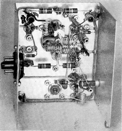
In the first photograph the 50-Mc. converter is at the right. Three 6CW4s are used. The first, a neutralized r.f. amplifier, is in the upper center portion of the picture. At the bottom right is the mixer tube, and to its left is the crystal oscillator. The 36 Mc crystal is in the left center, and above it is the antenna connector.
Turn now to the circuit diagram, Fig. 7. The tuned circuits L2 and L3, with the small coupling capacitor, C2, are used to give some selectivity in the r.f. amplifier grid circuit. The tuning screws for the coils are visible at the top of the first photograph. Similar circuits are used between the amplifier plate and mixer grid (L5, L6 and C3) and these are at the right side of the top view. The oscillator coil, L8, is in the lower center The mixer plate coil is in the lower right corner. The neutralizing coil, L4, is mounted horizontally, with its adjusting stud coming out of the side of the box. The i.f. output connector is in the upper right corner of the top view.
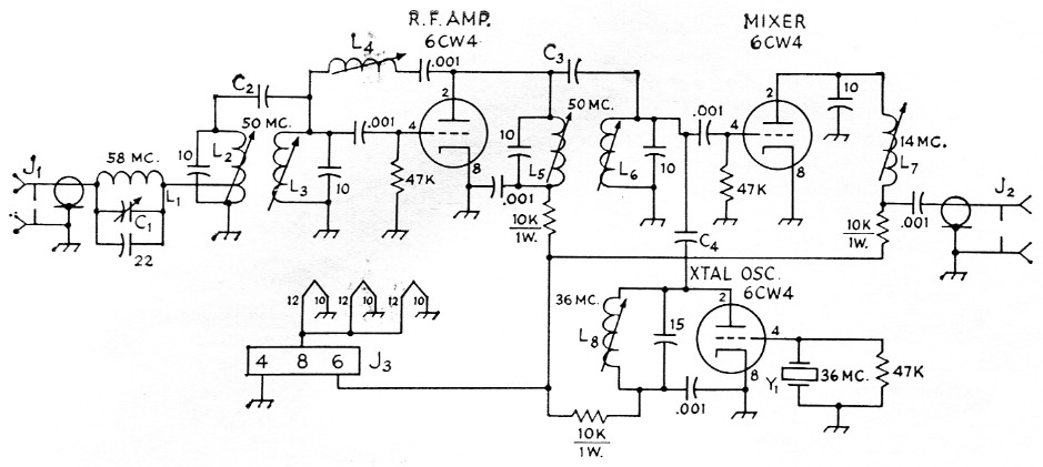
Fig. 7. Schematic diagram and parts information for the 50 Mc converter. Resistors ½ watt unless specified. Fixed capacitors are ceramic; decimal values in µF, others in pF.
| C1 | 3-30 pF mica trimmer. |
| C2,C3 | No. 22 insulated hookup wires 2 inch long, twisted together for approximately 1¼ inch. |
| C4 | Same, but 1 inch wires twisted for ½ inch. |
| J1 | Coaxial connector, SO-239. |
| J2 | Phono jack. |
| J3 | 8 pin plug (Amphenol 86-RCP8). |
| L1 | 5 turns No. 18, ½ inch diam., 8 t.p.i. (B & W No. 3002). |
| L2 | 10 turns No. 28 enam., close-wound on ¼ inch iron-slug phenolic form, tapped at 3 turns; 0.65 to 1.3 µH (Miller form No. 20A000RBI). |
| L3,L5,L6 | 8 turns No. 28 enam., close-wound on ¼ inch iron-slug phenolic form. Range 0.43 to 0.85 µH L3 set for 0.64 µH, L5 for 0.66, L6 for 0.73 µH (Miller coils No. 20A687RBI). L2 and L3 are 7/8 inch apart c. to c. L5 to L6 is ¾ inch; L to L8 is 7/8 inch. |
| L4 | No. 32 enam., close-wound 1/8 inch on ¼ inch iron-slug phenolic form; 3.8 to 8.5 µH, set for 6.9 µH (Miller coil No. 20A686RBI). |
| L7 | Universal-wound coil, 4.7 to 10 µH, set for 7.9 µH (Miller coil No. 20A826RB1). |
| L8 | 8 turns No. 32 enam., close-wound on ¼ inch iron-slug phenolic form; 0.67 to 1.25 µH, set for 0.94 µH. (Miller coil No. 20A106RBI). |
| Y1 | 36 Mc crystal (International Crystal Mfg. Co. FA-5). |
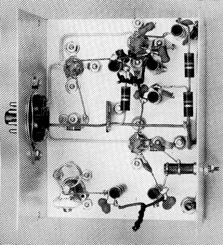
Bottom view of the 50 Mc converter, rotated vertically from the top view. The antenna connector and trap circuit are in the lower left corner.
The trap circuit, L1C1, is optional. Its purpose is to absorb Channel 2 video signals that might cause interference to 50 Mc reception, as the result of the second harmonic of the oscillator (72 Mc) beating with a Channel 2 TV sigpal. (72 - 14 = 58) Unless you are near a Channel 2 TV station you will not need the trap, and the connection from J1 can be made directly to the tap on L2.
The bottom view of the converter is inverted vertically from the top view. The antenna connector and the trap circuit are in the lower left corner. To the right are the coils L2 and L3, and the i.f. output connector. Near the middle is the r.f. amplifier socket, and in line with it at the top is the mixer socket. The crystal oscillator tube socket is at the upper left. The oscillator plate coil, L8, and the mixer grid coil, L6, are in the same plane to the right. Directly below L6 is the r.f. plate coil, L5. The i.f. output coil, L7, is in the upper right corner, connected througlr a shielded lead to the output connector in the lower right. The neutralizing coil, L4, is just above the latter, with its tuning screw projecting through the side of the box.
The coupling capacitors, C22, C3 and C4, are made by twisting insulated wires together to form small capacitances where needed. This is a convenient and inexpensive way of doing the job and since the values are not particularly critical, the twisted wires serve just as well as would a fixed or variable capacitor of conventional design.
Power is taken from the 150 volt and 6.3 volt sources in the power supply described last month. The 8 pin power plug, J3, is mounted in the side of the converter case. It should be positioned so that it will line up with the socket on the side of the tuner, or the similar socket on the modulator, if the tuner is not used.
The 144 Mc converter
The 144 Mc r.f. amplifier uses two 6CW4s instead of one, and an oscillator-multiplier system is needed for developing the injection voltage for the mixer. Hand-wound coils are used in the r.f. circuits, instead of slug-tuned coils. The first amplifier is a neutralized triode stage, as in the 50 Mc converter, but is followed by a grounded-grid stage, in the manner of the familiar seriescascode v.h.f. amplifier. The crystal oscillator works on 43.333 Mc, and drives a crystal-diode frequency tripler to 130 Mc. This injection frequency beats with signals at 144 to 148 Mc in the mixer, producing an i.f. of 14 to 18 Mc, as before.
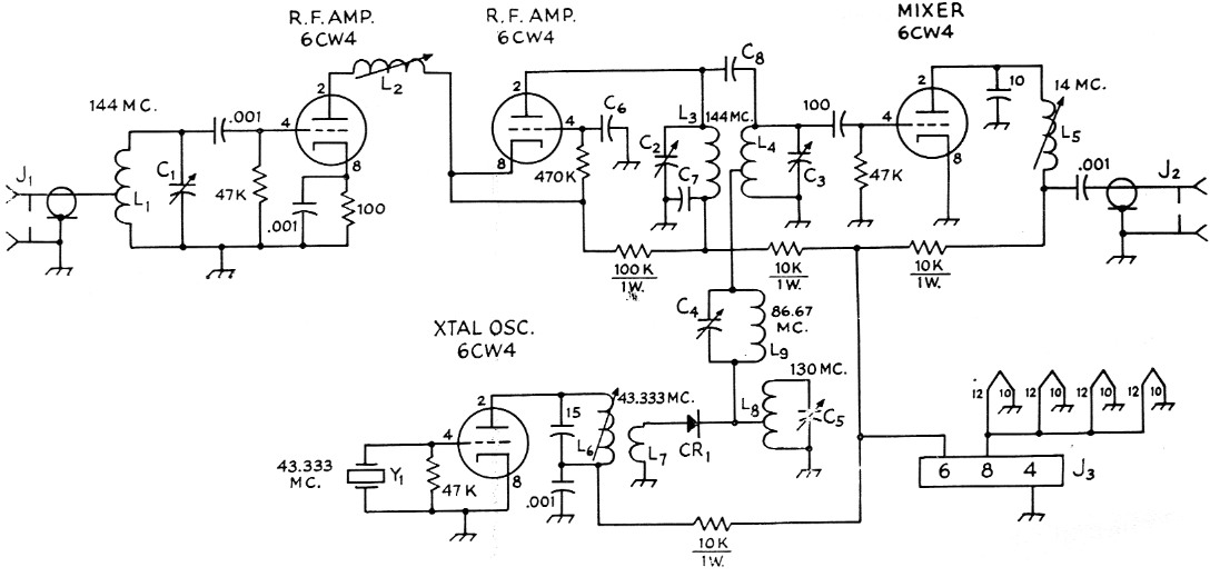
Fig. 8. Schematic diagram and parts information for the 144 Mc converter. Resistors ½ watt unless specified. Fixed capacitors are ceramic unless specified. Decimal values in µF, others in pF.
| C1,C2,C3 | 1-7.5 pF ceramic trimmer (Centralab 829-7). |
| C4 | 4-30 pF ceramic trimmer (Mallory ST-554-N). |
| C5 | 20 pF miniature variable (Hammarlund MAC-20). |
| C6,C7 | 1 nF button-type bypass (Centralab ZA-102). Do not use disk-ceramic or other wire-lead capacitors for these points. |
| C8 | No. 22 insulated hookup wires 1¼ inches long, twisted together for approximately 1 inch. |
| CR1 | Crystal-diode rectifier. Most available Types will work; DR-303, CK-710 and 1N34 tried. |
| J1 | Coaxial connector, SO-239. |
| J2 | Phono jack. |
| J3 | 8 pin plug (Amphenol 86-RCP8). |
| L1,L8 | 6 turns No. 18, ¼-inch diam. ½ inch long. Tap at 2½ turns. |
| L2 | 5 turns No. 28 enamel, close-wound on ¼ inch iron-slug form. Range 0.24 to 0.41 µH, set for 0.33 µH (Miller coil No. 20A337RBI). |
| L3 | 6½ turns No. 18, ¼ inch diam., 5/8 inch long. |
| L4 | 5 turns like L3, ½ inch long, tapped at 2 turns. L3 and L4 are parallel, 3/8 inch apart, c. to c. |
| L5 | Universal-wound coil, 4.7 to 10 µH, set for 7.9 µH (Miller coil No. 20A826RBI). |
| L6 | 9 turns No. 28 enamel, close-wound on ¼ inch iron-slug form. Range 0.58 to 1 µH, set for 0.82 µH (Miller coil No. 20A827RBI). |
| L7 | 1½ turns insulated hookup wire around L6. |
| L9 | 8 turns No. 18, ¼ inch diam., 5/8 inch long. |
| Y1 | 43.333 Mc crystal (International Crystal Mfg. Co. FA-5). |
Looking at the top view we see the r.f. amplifier and mixer tubes in line vertically at the right side of the converter. The crystal oscillator is at the lower left. The capacitor C5, which tunes the diode tripler circuit, is in the lower center of the picture. Just above is a grommet inserted in the hole over the trap capacitor, C4, of which more later. The antenna connector is in the middle of the top portion, and the i.f. output connector is in the upper left.
The bottom view was made by rotating the unit vertically, so the antenna connector appears at the bottom. The first amplifier grid circuit, L1C1, is in the lower right corner. Above it is the neutralizing coil, L2, mounted on the side of the box. The two tinned-wire coils side by side just above and to the right of center are for the amplifier plate, L3i and mixer grid, L4. To their left is the trap circuit, C4L9, tuned to the second harmonic of the oscillator, 86.67 Mc. The coil with its axis at right angles to these is L8. It is tuned to 130 Mc by C5, which appears in the upper center of the picture. The oscillator plate coil, L6, and the mixer plate coil, L5, are in the upper left and right Corners, respectively.
Interior of the 144 Mc converter. Details of parts arrangement are given in the text. The i.f. output from the mixer plate coil, L5, is brought through a shielded lead from the upper right corner, down the side of the picture and across the bottom, to the output connector, J2, at the lower left.
The diode multiplier and trap circuits
Frequency multiplication with crystal diodes may be new to many readers, but it is a simple and effective way of developing injection voltage in the v.h.f. range. Diodes do the job easily, and at less cost than a vacuum tube. The crystal works at low impedance, so it is connected be tween a loop (L7) around the oscillator coil and a tap on the tuned circuit L8C5. The latter should be fairly high-C, so that the desired harmonic, in this instance the third, will be accentuated, and other harmonics of 43.3 Mc suppressed.
There will be some energy at unwanted harmonic frequencies passed on to the mixer grid circuit. The trap, L9C4, is inserted in the lead to L4 to suppress the second harmonic, 86.6 Mc. As with the Channel-2 problem in the 50-Mc. converter. this trap circuit need be included only if local interference makes it necessary. In the Hartford area an f.m. station just above 100 Mc rode through around 14.2 Mc (100.8 - 86.6 = 14.2), but the trap removed the interfering signal completely when tuned to twice the crystal frequency. Removing the offending harmonic from the mixer circuit was the best way of handling the problem. A trap in the antenna circuit to absorb: the interfering signal was tried but it resulted Tn a slight deterioration of the converter noise figure at, 144 Mc.
Construction
The converters are built in aluminum Mini-boxes, 3 by 4 by 5 inches in size. The Nuvistor sockets have small metal tabs that are bent down against the underside of the chassis to provide grounding. These are clamped under washers by 4-40 screws and nuts on opposite sides of the sockets. The socket hole should be ½ inch diameter, with small notches filed out for the tabs. The ceramic trimmers in the 144 Mc converter, C1, C2, and C3, also require notched holes.
Leads in r.f. circuits should be as short as possible. Power wiring can be placed for neatness, but keep insulated power leads close to the chassis. Use terminal strips for holding resistors in place, and lugs bolted to the chassis for grounding.
Adjustments
The crystal oscillator is checked first. The meter in the bridge unit described last month, or any other 1 mA meter, may be used to measure oscillator plate voltage, or a voltmeter will serve if you have one for the 100 volt d.c. range. To use a 1 mA meter, connect a 100,000 ohm resistor in the positive lead and ground the negative lead. It is not important for this purpose that the 1000 ohm resistor shown in Fig. 6, Part 3, be included.
Working on the converters is easier if a 3 wire power cable with suitable plugs is used, rather than plugging the converters directly into the tuner or power unit. Tests may be made with all tubes in their sockets, as the dropping resistors in the plate leads prevent excessive current. Apply power to the converter. Touch the free lead of the 100,000-ohm resistor to the B-plus end of the oscillator plate coil. The meter indicates 100 volt d.c. for full scale. The voltage reading obtained will depend on whether the tube is oscillating or not. The oscillator current runs through a 10,000 ohm resistor, so the more current the tube draws the lower the voltage will be. When the circuit oscillates, plate current drops, and the indicated voltage rises.
Use of Ohm's Law will tell you what the plate current is, though this need not be found except as a matter of interest. With the core stud all the way up, the circuit probably will oscillate, and the meter indication will be around 0.7 (70 volt). Turn the stud into the coil, watching the meter. It will rise to around 0.9 (90 volt) and then drop suddenly as oscillation stops, to around 0.5 (50 volt). These represent actual plate currents of 8, 6, and 10 mA, respectively.
Readings may vary considerably from the above, due to differences in crystals and other parts. The important points are the gradual rise (increasing vigor of oscillation) and then the sudden dip as oscillation ceases. Set the slug for the highest reading (lowest oscillator plate current) at which the oscillator will start each time power is applied. The frequency can be checked with a calibrated wavemeter or grid-dip meter. It should be the frequency marked on the crystal, and no other.
The 50 Mc converter is now ready to receive strong signals, as soon as it is connected to the receiver or tuner. The latter has a cable and plug for connection to the i.f. output jack, J2. To use a communications receiver, make up a cable of any small coax, putting a phono-pin plug on one end. The other end connects to the receiver antenna terminals. This may require a coax fitting for some receivers, but most have screw terminals. Connect the inner conductor to the antenna terminal and the outer sheath to the ground terminal or the receiver chassis. Do this with the shortest possible leads, to keep down pickup of signals at 14 Mc. Now a 50 Mc signal is needed. This can be from a grid-dip oscillator, a nearby 50 Mc station, the harmonic of your transmitter, or ideally, a good signal generator. For any except the last, connect some kind of antenna to J1. A short piece of wire will do at first, and the length can be varied to suit the strength of the signal. Set the stud in L4 at about the middle of its range. Next, peak the screws in L2, L3, L5, L6 and L7 for maximum signal strength. Now disable the r.f. amplifier stage by disconnecting the 10,000 ohm resistor from L5, or by removing the heater lead from Pin 12 of the socket. Adjust L4 for minimum signal. Replace the heater or plate voltage and readjust all coils except L4 for maximum signal again. The converter should be close to optimum performance if everything has been done properly to this point. If the Channel 2 trap is used, adjust it so that no interference is heard from the local TV station. If the station is very near by, it may still be heard as long as the cover is off the converter case. It should disappear when the case is assembled. Recheck the adjustment of L2 and L3 after final adjustment of the trap.
Further work to improve weak-signal reception should be done with a noise generator, though satisfactory results can be obtained on weak signals if the work is done with care. The aim should be better signal-to-noise ratio, rather than merely greater signal strength. This will not be noticeable with the simple tuner, but it can be achieved with a communications receiver as the i.f. system. Using the receiver S meter, or the audio sound of a weak signal, tune for maximum signal with respect to noise.
Not every QST rig gets quite such extensive field testing, but this one went with the author on a 7000 mile field trip to the Rocky Mountain States early this summer. Several times we found 6 open, and had scores of DX contacts with nearly all sections of the country. In the June V.H.F. Party, with the help of K5TQP and K5UNK, W1HDQ/5 worked 18 ARRL Sections in all call areas except W1 and 2 from a spot near Albuquerque, New Mexico, using both phone and c.w. A communications receiver was pressed into service to deal with the heavy QRM, but the simple tuner was used during the first hour's work, just to prove that it would do the job. On 144 Mc, the entire station will outperform anything you could buy for twice t he money, and some of the rig's features cannot be found in anything ready-made at any price.
As a final check, put a 50-ohm resistor across J1. Observe the noise level. Now remove the resistor and put on an antenna system with 50 ohm feed. If the noise rises appreciably, you are hearing the external noise that limits your v.h.f. reception. The only improvement you can make from here on is to put up a bigger or higher antenna, or move to a quieter location.
Adjustment of the 144 Mc converter is similar, except that the multiplier tank circuit, L8C5, should be adjusted for maximum signal. External noise may not be discernible in quiet locations on 144 Mc, and the antenna check outlined for 50 Mc may be inconclusive. Adjustment of all r.f. circuits should be made carefully for greatest margin of signal over noise, using weak signals. The minimum-signal method of adjusting the neutralizing coil, L2, should be followed initially, but readjustment for optimum signal-to-noise ratio (or lowest noise figure, using a noise generator) may produce a worthwhile improvement. Do not use the second-harmonic trap, L9C4, unless it is necessary to eliminate f.m. interference, as this circuit introduces one more variable to complicate the adjustment procedure.
In most areas 2-meter activity is spread over more of the band than is the case with 50 Mc. The converter response can be made uniform across most or all of the band by tuning the i.f. output coil, L5, for maximum response near the high end or middle of the band. This coil affects only the gain of the converter; detuning it does not reduce the signal-to-noise ratio. The r.f. amplifier plate and mixer grid circuits, C2-L3 and Gil,-L4 have only a minor effect on noise figure, so they can also be "stagger-tuned " to soma extent to achiev t uniform response.
A fair final check on the 144 Mc converter performance is to detune the diode multiplier circuit, L5C5, and note its effect on the signal-to-noise ratio. If the r.f. amplifier is working properly it should be possible to detune this circuit so that the gain drops an S unit or two, before there is any effect on the signal-to-noise ratio observable on weak signals.
Receiver considerations
Selecting a communications receiver is a special problem for the v.h.f. man. He needs a good general-coverage dial, if he is going to tune the entire 14 to 18 Mc range for v.h.f. reception with converters. Most receivers are deficient in this respect, and some are almost useless. A good readable scale and a slow tuning rate are important attributes not likely to be found in low priced receivers. Often a used receiver of good quality is a better investment for the v.h.f. mau than a new one of moderate price.
The ham-bands-only receiver is out, as it wei not tune enough freiiuency range on any amateur band to give satisfactory i.f. coverage when used with these converters. The crystal oscillator and i.f. output circuits of the converters can be modified to permit use of the 10-meter range on such receivers, but performance and dial characteristics of some communications receivers are not particularly good on the 2S-Mc. range. Even the best do not cover t'ie four-megacycle spread needed to tune an entire v.h.f. band with a single converter crystal, with the exception of those which have a special range just for this purpose.
Some receivers cover 14 to 15 Mc on one range. With these you can change converter crystals in order to tune successively-higher 1 megacycle segments of a v.h.f. band. Examples: For 50 to 51 Mc, you use the 36 Mc crystal shown. To cover 51 to 52 Mc, you merely put in a 37 Mc crystal. To cover 144 to 145 Mc, you need the 43.333 Mc crystal specified. Replacing this with one at 43.667 Mc gives a 131 Mc injection frequency, and coverage of 145 to 146 Mc. No change other than the crystal need be made for at least two megacycles coverage with such a receiver.
Many experienced v.h.f. men use a special technique with two-dial general-coverage receivers. They tune the low end of a v.h.f. band with their dials set the same as for tuning the 14 Mc band, and they tune with the bandspread dial. (14.000 Mc is 144 Mc, 14.1 Mc is 144.1 Mc, and so on.) When they reach the high end of the bandspread range, they reset the general-coverage dial higher, so that a full turn of the band-spread dial gives another 300, 400 or 500 kc of calibrated coverage. This will not give exact dial calibration in tuning progressively higher ranges, but it makes tuning for weak signals easier than when the fast-moving general-coverage dial is used. With receivers having crystal calibrators, it is a simple matter to keep a fairly accurate check on the frequency being tuned in this manner.
So there you have it - the first complete v.h.f. station to be described in many a year, if we exclude the simple transceivers of the self-contained type. You can build the works yourself, receiver and all, and you will have the base on which to build for more power or better receiver performance later on. "Will it work?" the newcomer may ask. Perhaps the best answer is the results that the rig has delivered to date.
At various stages of its design and construction, the station was used, as a whole or in parts, for many hours of operation both 50 and 144 Mc at the home stations of W1HDQ and W1YDS. Some practice with the simple tuner is needed to learn how to use it with maximum effectiveness, but we both agree that it is capable of hearing at least anyone we could work on either band with 15 watt input. The voice quality with the transmitter is good, and the c.w. signal is above reproach. And the simple receiver is quite capable of handling c.w. and s.s.b. signals in usable fashion, which is more than can be said for some v.h.f. "packaged stations" now available commercially.
As we write, requests for drilling templates are coming by the dozen in every Headquarters mailbag. Nobody builds anything any more? Don't you believe it - there are plenty of hams who like to build gear, and hundreds of them are already at work on all or part of this station. They will be better hams for it.
Notes
- Templates for drilling the principal surface of each box are available at no cost from the ARRL Technical Department. Please send a stamped self-addressed envelope and state which templates you want, giving the equipment and the issue of QST. Templates are also available for the tuner, Part 1, and the two transmitters, Part 2, described in the July and August issues of QST, respectively.
Tape the template to the surface of the chassis and center-punch the holes. Sizes are given for all the holes, but it is well to cheek the parts you have to be sure that they require holes of the sizes given on the template. Different makes from those used in the original way may require minor changes in hole shape, size or location.
Glossy prints made from the original negatives can be supplied for any equipment built in the ARRL laboratory, at a cost of $1.50 per print. Be sure to give the issue and page number of the photograph needed.
Edward P. Tilton, W1HDQ.