A filament choke for grounded-grid amplifiers
Optimized design for 3.5-30 Mc.
Impedance measurements on various suggested designs of filament chokes for grounded-grid amplifiers showed rather poor performance on one or more bands in the 3.5-30 Mc range. This situation prompted a bit of lab work, leading to the design shown in this article.
With grounded-grid linear amplifiers becoming more and more popular, there is increasing need for a good filament choke. A typical circuit configuration for a grounded-grid amplifier using a filament choke is shown in Fig. 1. The choke should offer sufficient impedance to elevate the cathode above ground potential for r.f. and, at the same time, be made of heavy enough wire so that there is negligible loss of filament voltage in the choke. This means that in a choke for tubes such as the 4-250, PL6580, PL6559, and 4-400 - which draw approximately 14 amperes of filament current - No. 14 or heavier wire should be used. Correspondingly smaller wire can be used for tubes that take less filament current. Two chokes can be paralleled in applications which require larger current-carrying capacities.
As shown in Fig. 1, a choke of this type is inserted in series with the filaments of the grounded-grid stage. The input impedance of a grounded-grid amplifier is usually in the range of 100 to 400 ohms, depending on the type of circuitry and tube being used. If the data for the tube in grounded-grid operation is available, the input impedance can be calculated from
![]()
This impedance, which is that of the tube or tubes alone, is purely resistive when the plate circuit is properly tuned. However, it is shunted by the impedance of the filament choke, and since the choke impedance will be principally reactive, it is desirable that the choke reactance be as high as possible compared with the tube impedance. Considering the practical aspects of choke construction for a wide frequency range, such as 80 to 10 meters, experiment shows that a choke inductance of about 45 Al. is about as much as can be obtained. This is high enough for satisfactory operation on bands as low in frequency as 3.5 Mc.
The problem is to get the required inductance with the minimum wire length. Obviously a core material with high permeability is desirable, as this yields the most inductance for a given coil. Ferrite cores lend themselves nicely to this application, as they have high permeability and are available in various diameters.(1) The choke can have a bifilar winding; that is, two wires wound side by side on the ferrite core. The enameled coating used on the wire provides sufficient insulation to prevent shorting between turns.
A well-designed wide-range choke will usually have its greatest effect on the input impedance at the lower amateur frequencies, simply because its reactance decreases with frequency. If the driving power is marginal, it may be necessary to use some type of matching network to match the output impedance of the driver to the input impedance of the amplifier. Any one of several methods can be used, the pi-network probably being the most flexible.(2)
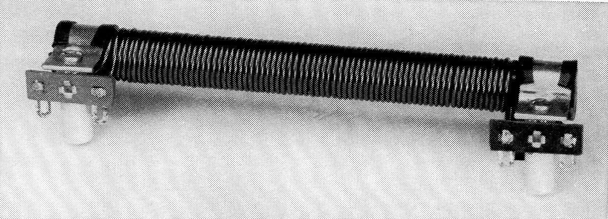
Bifilar filament choke using ferrite core. When mounted in place, the choke is supported off the amplifier chassis by the ceramic insulators on the ends.
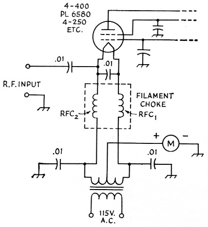
Fig. 1. Typical filament circuit for grounded-grid amplifier using a tube having a directly-heated cathode. RFC1 and RFC2 can be separate windings, but bifilar construction is generally more compact and gives better performance.
Construction
Construction of the choke shown in the photograph is straightforward and fairly easy. Two side-by-side 58-inch lengths of No. 14 wire are wound on the ½ inch-diameter ferrite core. The core material, available in 7½ inch lengths, is Lafayette Radio type MS-333, Catalog No. 600. An over-all length of only 6½ inch is needed. The core may be used intact, but the excess can be cut off by first scoring the complete circumference of the core with a hacksaw or file, and then sharply but gently striking the core at that point. The ferrite material should break clean. For those who are not quite so daring, the much more tedious method of sawing the core with a hacksaw is recommended. The core should be covered with a single layer of Scotch electrical tape, and then the 36 turns of wire should be wound on tightly. All that remains to be done then is to fasten the two wires to the three-lug bakelite terminal strips mounted at the ends of the ferrite rod. These terminal strips are held in place by 3/8 inch cable clamps (Allied Radio 41-H-853, Cinch-Jones CC-161-6, or Herman Smith 835). The whole choke assembly is supported by two cylindrical ceramic standoff insulators (Millen 31007) which in turn mount to the amplifier chassis.
The impedance components of the choke at various ham-band frequencies are given in Table 1. This choke will have adequate impedance to raise the filament of a directly-heated tube above r.f. ground potential on all bands from 80 through 10 meter. It is the best of several designs tried experimentally. Larger inductance (more turns) will result in higher reactance at the lower frequencies, but is accompanied by a deterioration in performance at the high end. The high-frequency range can be extended by decreasing the number of turns, but at the expense of to-low reactance at 3.5 Mc. The choke is self-resonant between the 7 and 14 Mc bands.
| Frequency in Mc. | Shunt Resistance Ohm | Shunt Reactance Ohm |
|---|---|---|
| 3.50 | 28 k | 1300 (inductive) |
| 7.0 | 70 k | 2200 (inductive) |
| 14.0 | 100 k | 8000 (capacitive) |
| 21.0 | 100 k | 3200 (capacitive) |
| 28.0 | 70 k | 2700 (capacitive) |
| Q at 3.50 Mc = 32. | ||
As shown by Table 1, the equivalent parallel resistance of the choke is high throughout the frequency range. This means that the actual r.f. power loss in the choke will be negligibly small, since even the smallest value of shunt resistance is of the order of 50 to 100 times the input resistance of the amplifier tube or tubes. Thus in the worst case the choke dissipates only about 1 or 2 per cent of the driving power.
Notes
- Use of a core of the type shown in the photograph was suggested by Henry A. Voorhees, W4CPI.
- Orr, Rinaudo and Sutherland, "The grounded-grid linear amplifier," QST, August, 1961.
Kenneth C. Lamson, W1ZIF.