E-Z-up antenna for 75 and 40
Simple construction for inverted-V dipoles.
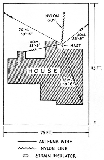
Fig. 1. W5LST's layout for effective 40 and 80 meter antennas on a small lot. The two "drooping" dipoles are fed in parallel with a single coax line. Nylon-line extensions are used to reach convenient anchorages.
Full-size dipoles for the 75 and 40 meter bands occupy more space than is conveniently available on the 75 by 113 foot lot at W5LST. The increasing popularity of the "drooping," or inverted-vee, dipole antenna among amateurs led us to investigate it for our somewhat crowded conditions. Based on the electrical design of Glanzer,' this system has performed meritoriously at W5LST. Requiring only one support, it was surprisingly easy to erect, gives a satisfactory s.w.r. over the phone bands and, importantly, the cost was less than thirty dollars complete. A plan-view sketch is shown in Fig. 1.
The mast
The mast is a telescoping Channelmaster, capable of 50 foot height, but extended only to 35 feet. Extending the upper sections to less than their full lengths gives rigidity to the mast, and has apparently eliminated the need for guys on each section, as recommended by the manufacturer. To date this mast has withstood gusts of 50 miles per hour without a shudder; it is yet to be tested in a real gale, however.
As shown in Fig. 2, a 9 foot length of 3 inch pipe is cast in concrete with 6 feet of its length extending above ground. Three pairs of clamps, such as those used on chain-link fence, secure the mast to the upright standard. During erection, these clamps are loosened and all three lie at the base of the standard, so that the mast need only be lifted about 6 inches to be put in place. When the mast is in place, the clamps are raised and tightened.
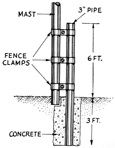
Fig. 2. The mounting for the antenna mast. The 9 foot pipe is guyed temporarily while the concrete is poured.
Rigging
Except for the antenna conductors, all rigging is of nylon line of 500 pound test. A halyard is reeved through a pulley of suitable size which is wired securely to the top of the mast. The two ends of the halyard are made fast to a harness snap which, in turn, supports the center of the antennas. Provision of this halyard has proved to be a great convenience in permitting inspection of the antenna connections and the adjustment of tension in the wires without the necessity for lowering the mast.
Nylon line has a tendency to ravel at its ends but this problem is easily solved. Most fastenings were made with two half-hitches, followed by sewing the end of the line to itself with thread, as shown in Fig. 3A, and doping with one of the quick-drying model-airplane cements.
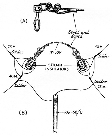
Fig. 3. The halyard and feeder arrangement. The coaxial cable is sealed securely with polyethylene tape after the connections are made. The harness snap of A at the end of the hoisting halyard engages the bridle between the two insulators in B.
Some weeks after the initial installation, it became apparent that some additional stabilization of the mast against occasional strong northerly winds would be desirable. Accordingly a nylon line was run from the harness snap at the top of the mast to a convenient anchor in the back yard, which happened to be the top of the children's swing set. Experience seems to show that the antenna wires, together with the additional nylon line, stabilize the mast against aerodynamically-excited vibration, without any appreciable strain on the antennas.
The antennas
As shown in Fig. 3, the two antennas are connected in parallel at the top of the mast. The lower ends are connected to convenient tie points so that the two legs of a given antenna are more or less in a straight line. To our great surprise, very little effect is produced by moving the ends of the antennas either horizontally or vertically. There is apparently negligible electrical interaction between them as indicated by the s.w.r. bridge.
Pruning of the antennas is, as always, desirable. In our case, the optimum lengths of each leg turned out to be 33 feet 9 inch for 40 meter and 59 feet 6 inch for 75 meter. Fig. 4 shows the performance of the antennas on 40 and 75 as measured by a Heath s.w.r. bridge. Although the antennas tune sharply, they are usable over the entire phone band in each case, and it would be difficult to imagine a better performer on the lower-frequency bands than this simple antenna system.
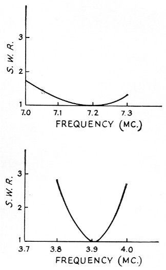
Fig. 4. S.w.r. curves as indicated by a "Monimatch"type s.w.r. indicator.
Notes
- Glanzer, "The inverted v-shaped dipole," QST, August, 1960.
John C. Allred, W5LST.