VFO stability - recap and postscript 1
An Examination of Some Design Principles, Old and New
In the course of looking into some aspects of c.w. keying it became desirable to build an experimental v.f.o. for obtaining quantitative information on stability. While there is an extensive literature on oscillators, performance data of a kind that is of interest in the keying problem appear to be scarce. We set out, therefore, to get some figures in areas where they were needed.(1)
The experimental work uncovered a few things which, so far as the writer knows, have not been treated before. In addition, others were found not to have had sufficient emphasis placed on them. It therefore seems to be an appropriate time to review the principles of v.f.o. design and construction, with particular reference to frequency stability. Although the present article is concerned with vacuum-tube applications, a corresponding look has been taken at transistor v.f.o. operation, and those aspects peculiar to transistor oscillators will be discussed in a subsequent article.
Overall Approach
It would be pointless to assert that there is only one solution to the many problems in v.f.o. design. Examples of equally good results secured by alternate methods always can be produced. However, a choice of systems has to be made, and after considering the several conditions that must be met for good keying, the conclusion was reached that the conversion-type v.f.o. had enough advantages to overbalance its disadvantages.
In s.s.b. equipment, where the conversion system is a practical necessity, the tunable oscillator commonly operates in the neighborhood of 5 Mc., a frequency which also was suitable for our purposes. A guinea-pig v.f.o. therefore was constructed according to the skeleton diagram of Fig. 1. As it was intended to be a crystal substitute for transmitters in which frequency multiplication is used for getting on the amateur bands above 3.5 or 7 Mc., it was designed for primary output in the 3.5 Mc. band with provision for doubling frequency to 7 Mc. Thus it could replace both 3.5 and 7 Mc. crystals.
This, incidentally, is not the best way to utilize the conversion system, since instabilities are multiplied along with the frequency. However, it does not suffer in comparison with the non-conversion v.f.o. on this point.
A critical look at the transmitting v.f.o. under the right illumination brings some aspects of design and construction into different perspective. This article is specific on points that usually are treated only vaguely, gives a different slant on others that have become a matter of rote, and introduces new wrinkles for unearthing and curing defects that often go uncorrected.
Multiplication of tuning rate on different bands is always a problem when frequency multiplication is used. An adequately slow rate on 28 Mc. requires an extremely limited tuning range on 3.5 Mc. A compromise was reached here by making use of inexpensive surplus crystals spaced at 25-kc. intervals in the conversion oscillator. With a tunable-oscillator range of about 30 kc. (for overlap) the tuning range is 200 kc. per crystal on 28 Mc., 150 kc. on 21 Mc., 100 kc. on 14 Mc., and so on. This fits actual operating practices pretty well from 7 Mc. up, but is restrictive on 3.5 Mc., where six crystals will cover only the first 150 kc. of the band.
Oscillator Requirements
Amateur operation is like that of no other service, in that it consists of relatively short periods of communication which are rarely on the same frequency for more than an hour or so, and usually much less. We move around in our bands, sometimes only a few kilocycles but more often over a considerably wider range, and we jump from band to band. What we need, then, is the best possible short-term stability.
The question of whether a v.f.o. will hold within some stated number of cycles over a period of weeks or months at an untouched dial setting is of little practical importance; the dial isn't going to be left alone for very long if much operating is done. However, a v.f.o. that has good short-term stability usually also will do very well in holding long-term calibration. In fact, it can do better than most read-out devices or the operator's ability to reset them.
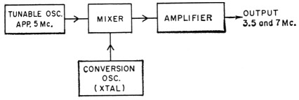
Fig. 1. Block diagram of the conversion-system v.f.o.
Causes of Instability
The principal causes of an unwanted shift in the frequency generated by an oscillator are:
- Voltage variations - a change in the voltage applied to any eleWent of the active device, be it tube or transistor, is accompanied by a change in characteristics that reflects as a variation in frequency;
- Loading - a change in the load on an oscillator changes its operating conditions and in turn causes the frequency to shift;
- Temperature - the electrical values of all components vary with temperature, and these variations in turn affect the frequency; and
- Shock and Vibration - these, too, cause changes in the electrical values of components or the circuit as a whole.
An exceedingly annoying effect, not readily classified, is an unpredictable sudden jump in frequency usually associated with minute instabilities in components (particularly fixed capacitors and resistors) or construction.
It is well established that the circuit-design feature of most benefit, especially in reducing the effects of voltage changes, is loose coupling between the tube and frequency-determining circuit. To make the most of this, the tuned circuit must have a high operating Q and the tube must have a high value of transconductance. If the loose-coupling principle is observed the rest is theoretically just detail. However, it is these "mere" details that make the difference between a good v.f.o. and a poor one.
The Oscillator Tube
All the oscillator circuits in common use are basically triode circuits, whether or not the tube has more than one grid. The widely used "hot-cathode" oscillator is generally a Hartley or Colpitts having the anode grounded for r.f. When a screen-grid tube is used as an electron-coupled oscillator, Fig. 2, the screen is the principal anode, with the plate helping out to an extent that depends on the form that the plate circuit takes. If the plate circuit is tuned to the generated frequency, the plate itself is partially disconnected from the oscillator circuit because of the plate-to-ground impedance of the tuned circuit? Because slight detuning of this circuit reduces the impedance, detuning puts the plate more-or-less in parallel with the screen. The effect of varying an output tuning control, then, is to change the tube characteristics - inevitably accompanied by a change in the oscillator frequency(3)
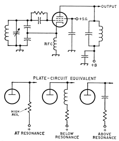
Fig. 2. Electron-coupled oscillator with tunable plate (output) circuit. The three possible equivalents of the tunable circuit are shown in the lower drawings. Since the a.c. component of plate current has to flow through the plate tank, the effect of varying the plate tuning control is to change both the amplitude and phase of the plate's contribution to the oscillator operation.
Very frequently the plate circuit is nominally a resistor or r.f. choke, as in Fig. 3. This "untuned output circuit" is actually a capacitive reactance (consisting of the oscillator tube's output capacitance, the following tube's input capacitance, and stray capacitance in the circuit) in parallel with the input resistance of the following amplifier. Unfortunately, tuning the following tube's plate circuit usually causes a change in its input capacitance or resistance, or both. This is turn affects the oscillator frequency, since the e.c.o. plate load is not constant.
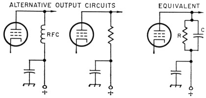
Fig. 3. "Untuned" output circuits for the e.c.o. The equivalent is the same in both cases, since an r.f. choke (at its useful frequencies) acts as a small capacitance in parallel with a large resistance. In the circuit at the right, R is composed of the plate resistor (or the choke equivalent resistance) in parallel with the input resistance of the following stage. C includes all tube and stray capacitances.
What this adds up to is that the electron-coupled oscillator by itself is not the answer to all stability problems associated with reaction of following-stage operating conditions on the oscillator frequency. The clue to effective isolation lies in the use of a buffer amplifier so designed that nothing that may happen in its output circuit can have any effect whatsoever on the oscillator. Practically, this means that the buffer must be used for stability only, not for power output. It should not be asked to develop more than a couple of volts of r.f., and that only into a circuit whose constants are not subject to variation. Gain, either in power or voltage, is the last thing that should be expected of a true buffer.
A pentode amplifier - one designed for use in receiving applications and therefore having very low plate-grid capacitance - will provide well-nigh perfect isolation in a properly-designed circuit. Tube structures suitable for this are to be found in several dual tubes, the other structure being a triode which, in general, will have excellent characteristics as an oscillator. A mediumla triode and sharp-cutoff pentode make a good combination; the latter usually has lower grid-plate capacitance than the remote-cutoff type. Better overall performance can be expected from such a pair than from the tetrodes or pentodes commonly used singly as e.c.o.s. No more components are needed than for the e.c.o., and there is still only one tube envelope.
After comparing characteristics of the various triode-pentode types available, the 6U8A was selected for the v.f.o. discussed here. It has a high-transconductance triode(4) and a pentode section with as low grid-plate capacitance as any.
The oscillator circuit
Theoretically, equivalent results can be obtained from any of the several basic oscillator circuits. The writer prefers the Colpitts, since it allows the use of large shunting capacitances directly across the tube elements. The capacitance values are usually about the same in either the straight high-C circuit or the series-tuned version; in this case, the high-C arrangement was used in the thought that a relatively small coil could be made more resistant to vibration. In the actual circuit, Fig. 4, the number of components in the tank has been reduced to a minimum; the smaller the number, the fewer the chances of running into random frequency variations of the type mentioned earlier.
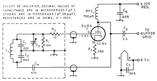
Fig. 4. High-C Colpitts oscillator. See text for discussion of functions and values. Dashed line represents the shield box shown in Fig. 5.
C1, C2, C4, C5 Silver mica.
C3-Capacitance range dependent on bandspread range desired. Capacitor in Fig. 5 is 50 pF (Millen 19050).
Ca, C7 Disk ceramic; value not critical, but should have low reactance at operating frequency.
L1 For 5 Mc., approximately: 9 turns No. 18, 1 inch diem., 8 turns per inch (Miniductor 3014 or equivalent).
For 2.5 Mc., approximately: 19 turns No. 20, 1 inch diem., 16 turns per inch (Miniductor 3015 or equivalent).
R1, R2, R3 ½ watt composition.
RFC: 750 µH r.f. choke (Millen 34300-750).
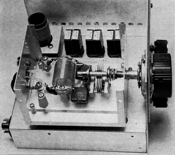
Fig. 5. Oscillator tank circuit construction. The container is a 3 × 4 × 5 inch Minibox. The components enclosed in the dashed box in Fig. 4 are mounted on a rectangular plastic plate supported at the corners by 3/8-inch pillars. The fixed tank capacitors rest flat on the plastic plate, and all components are solidly supported.
One way of looking at the question of light coupling between the tank circuit and the tube is that the tube must see a low impedance, especially as viewed from its plate circuit. That is, the effective amplification in the tube must be low - just great enough to sustain oscillation. For this reason the L/C ratio must be low, and in Fig. 4 the coupling is further reduced by making the plate section of the capacitance, C2, larger than the grid section, C1. Although the effect of varying the capacitance ratio was not investigated extensively, the 2-to-1 ratio is a quite satisfactory one for the 6U8A triode, as judged by results.
Hum Modulation
One undesirable feature of the hot-cathode circuit arrangement is that heater-cathode leakage or capacitance often causes frequency modulation of the oscillator at the supply-frequency rate. Although this becomes more apparent at the higher multiples of the oscillator frequency, it is sometimes observable even at the fundamental. It can be avoided by grounding the cathode, as is done in Fig. 4. If only a small frequency range is to be covered the tuning capacitor, C3, can be simply a "vernier" across one or the other of the main tank capacitors; it will not affect the capacitance division to any noticeable extent. In this case it is across C1. If a larger tuning range must be covered the tuning capacitor could be across the whole tank. This would require that its rotor be insulated from ground. Alternatively, a split-stator capacitor could be used.
With the grounded-cathode circuit it is necessary to use parallel plate feed. The choke should be one that is good at the operating frequency, but otherwise it is not a critical item. Neither is the plate blocking capacitor, C4, although the smaller its capacitance the looser the coupling between the plate and the tank. A silver mica capacitor is advisable for best stability.
Platevoltage stability
The circuit features already discussed are the primary ones in determining the frequency stability with changes in plate voltage. This point has had so much attention over the years that it hardly needs more discussion. The question is largely academic, if the oscillator is not keyed or otherwise turned on and off, because the plate voltage ordinarily will be stabilized by a voltage regulator. However, this is no excuse for neglecting to make the best possible oscillator in the first place. The circuit should be designed for as good voltage stability as it is possible to get - before adding the VR tube or other means of regulation.
It is characteristic of oscillators that the maximum rate of frequency change with a change in plate voltage occurs at the lowest voltages. For this reason the voltage should be as high as is consistent with the somewhat conflicting requirement that for minimizing tube heating the power input should be low. With a small triode such as the one in the 6U8A, which has a rated plate dissipation of 2.5 watts, 105 volts is a reasonable value for the plate voltage. In the circuit of Fig. 4 the plate input is 0.7 watt.
Heatervoltage stability
Although plate-voltage variations resulting from changes in line voltage are easily overcome with a simple regulator, the line-voltage variations continue to be transmitted to the tube heater. The oscillator frequency is, in general, sensitive to such changes. However, the reaction is not quite the same as that caused by a change in plate voltage. If the line voltage fluctuates as it often does when the load of a power amplifier is keyed on and off - the reaction usually takes the form of a fairly rapid, although not instantaneous, frequency change followed by a nottoo-slow drift. The effect of heater voltage on frequency has too often been ignored in writings about oscillator stability, although it has had attention in a recent article.(5)
In the early work with the oscillator described here, frequency shifts of the order of 170 cycles, over a period of 20 to 30 seconds, were found to occur when the line voltage was changed rapidly from 100 to 130 volts, even though the VR regulator held the plate voltage constant. A separate heater supply was installed with Variac control, and it was found that the frequency variations were caused entirely by heater-voltage changes. Furthermore, the frequency changes were much too rapid to be attributed solely to temperature changes in tube elements. The oscillator plate voltage at this time was 30 volts (through a dropping resistor from a regulated source) and the grid leak, R1, was one megohm. Both values are in line with the "maxim" that low plate voltage and a high-resistance grid leak should be used for best stability.
In looking for ways to reduce heater-voltage effects it was found that a higher plate voltage, 105 volts directly from the VR tube, and a lower grid-leak resistance, 10,000 ohms, effected a worthwhile improvement. Also, it was observed that tubes varied in their sensitivity to heater voltage, and in particular that the 6U8A was markedly superior to the older 6U8. This may be related to the difference in heater construction in the "controlled-warm-up" tubes.
Further investigation showed that the rectified grid voltage of the oscillator reacted almost immediately to a sudden change in heater voltage. Since this presumably could only be caused by a change in amplification, it suggested a possible remedy, negative feedback, to stabilize the amplification. The simplest method of adding negative feedback, an un-bypassed cathode resistor, was tried with encouraging results. This resistor is R3 in Fig. 4. The more resistance the better, up to the limit where the oscillator will refuse to start when plate and heater power are turned on simultaneously. A value of 390 ohms was found to be optimum, in the sense that the improvement was almost maximum and the circuit started willingly with any of a collection of tubes. The fact that the resistor adds d.c. bias is incidental; bypassing the resistor for r.f. destroys the action completely.
As a result of these several changes, the frequency shift with the same change in line voltage was reduced to a total of 5 to 10 cycles, depending on the particular 6U8A in use.(6) The major improvement came from the cathode resistor. Cathode-resistor stabilization was subsequently applied to triode oscillators in other equipment with equivalent results.
A beneficial effect of this type of stabilization is that rapid variations in frequency are eliminated. If the line voltage is suddenly shifted 20 or 30 volts in either direction, there is no detectable change in frequency for a few seconds, and if the voltage is quickly restored to the original figure, no frequency change occurs at all. In other words, the oscillator is impervious to transient "bumps" in the line voltage. If the line voltage is shifted and then maintained at the new value, there is a very slow drift beginning after a few seconds. However, since the total frequency change is small the fact that the frequency has shifted is seldom perceptible to the ear, either as a change in c.w. beat-note frequency or as a change in the "quality" of an s.s.b. signal. The residual shift is probably an actual temperature effect, which would be expected to be slow.
Frequency drift
The slow change in frequency - "drift" with changes in temperature has several possible causes:
- Heating of the oscillator tube, which causes small changes in interelectrode capacitances and operating characteristics.
- Changes in the electrical values of components because of changes in the temperature of their surroundings.
- Similar changes in component values caused by direct conduction from a high-temperature source such as the tube.
- Changes in electrical values of components because of internal heating from current flow.
Tube heating
The tube generally gets blamed for a major share of the drift, especially the "warm-up" drift. In many cases it actually is responsible, but not for reason (1) listed above. What really happens in oscillators constructed according to the mania for short leads is that the tube is too close to the tank components; the heat it generates is only too effective in raising the tank-circuit temperature.
This is not a new thought by any means.(7) However, the fact that there are two ways by which tube heat can be transferred to the tank does not seem to have been emphasized. The obvious one is by radiation and convection from the tube envelope. In the first layout tried for the oscillator being discussed, the tank coil and tuning capacitor were mounted exactly as shown in Fig. 5, but the tube socket was mounted on the back wall where the two leads now leave. The tube extended horizontally outside the box, so the wall protected the tuned circuit from radiated heat. C1 and C2 were mounted right at the socket, with leads of almost zero length. A number of drift runs were made, with curves A and B, Fig. 6, being typical. The frequency changed 350-400 cycles during the first 20 minutes, after which the oscillator stayed nominally on frequency (within 50 cycles) for the next two hours. As the cover was not on the box during these runs the tank circuit components were in open air. Room temperature was essentially constant during the period.
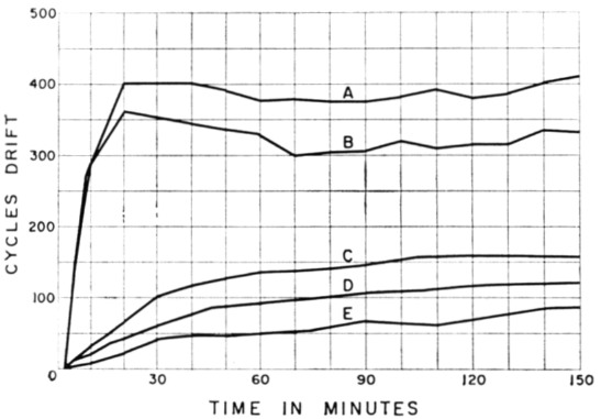
Fig. 6. Typical frequency drifts with short leads between fixed tank capacitors and tube (A and B) and with the tank-circuit layout shown in Fig. 5 (C, D and E).
On the assumption that the rapid initial drift was caused by heat conducted through the tube pins, C1 and C2 were moved to the location shown in Fig. 5, between the coil and tuning capacitor. The character of the drift was changed completely as a result of this simple modification, as shown by curves C, D and E in Fig. 6. It would be difficult to say just where the "warm-up" period ends, but the important point is that at no time is the drift rapid enough to be noticed in ordinary operation. A "cold start" in these tests means that all power to the oscillator had been off for at least 12 hours prior to the test, and that measurements were started 2 minutes after turn-on. This allowed just enough time for the tubes to get their operating characteristics up to par.
From a practical operating standpoint there appears to be little basis for choice between the two sets of curves after a 30-minute warm-up. But during that 30-minute period the C-D-E set is far better; the transmitter can be put into operation immediately, with no annoying initial drift. The total drift is likewise less over a longer period of time, but the difference is hardly enough to be perceptible in the setting of the tuning dial.
In considering the curves, it should be kept in mind that the tank circuit was well ventilated in these tests, and was not subjected to general heating such as would occur in the stove-like atmosphere of a crowded complete transmitter. In other words, the curves show primarily the effect of heat conducted from the tube to the tank.
Tube capacitances
The remaining effect of tube heating - that is, the changes in interelectrode capacitances of the tube as it warms up - was investigated by the simple process of allowing the oscillator to stabilize over a period of several hours, then removing the oscillator tube and quickly plugging in a cold one.
The maximum frequency drift that could be attributed to tube changes alone, in several tests of this type, was approximately 25 cycles at a test frequency of about 5 Mc. The time required for the new tube to settle down was 15 to 20 minutes. This cause of drift seems to have been somewhat overrated.
Components
If the tube itself is a negligible factor in frequency drift - as it should be in a high-C circuit - the onus falls on the other circuit components. Since the electrical values of all components are affected by temperature, two things logically should be done: first, select types of components that are least affected; and second, keep their temperature as constant as possible, especially during an operating period.(8) (In line with the earlier assertion about calibration, it does not matter if the frequency is different at the same dial setting in different operating periods; what we want is a v.f.o. that will hold its frequency better than the other fellow's receiver does while we're in contact with him.)
Silver-mica capacitors have quite low temperature coefficients, as is well known. The ones shown in the oscillator tank photograph are the old-style molded "postage stamp" type. The more modern "dipped" type was substituted, but the drift was greater. We have no explanation for this, since temperature-coefficient data were not available on the postage stamps and they could not be compared with the dipped variety in this respect. The latter appeared to be within ratings. It is to be expected that there will be some variation between units, even of the same type.
The Miniductor-type coil showed marked superiority to coils of the same inductance wound on either ceramic or low-loss bakelite forms. Slug-tuned coils are worse than equivalent coils without slugs, since the iron has a rather poor temperature coefficient. Slug tuning offers a convenient way of adjusting the inductance, but this is only a minor advantage in a home-built v.f.o. Miniductor-type coils can easily be pruned, and the pruning needs to be done only once. Furthermore, the Miniductor has the highest Q, around 150 at 5 Mc. as against 50 or less for the slug-tuned coils, which is a definite advantage in oscillator design.
Components not directly in the tank, such as R1, C4, C5, and RFC1, have an almost negligible effect on the frequency. The frequency change amounted to only a few cycles when hot air from a hair dryer was funneled directly on them. Similar treatment of the tank components, L', C1, C2 and C3, showed frequency changes 10 to 30 times greater. This is purely qualitative, as there was no means available for measuring the temperature rise in an individual component, but the comparison is believed to be useful.
Internal Heating of Components
Temperature rise from internal heating can be minimized by using components amply rated for the job. The only resistor of any consequence in an oscillator circuit of this type is the grid leak, and since the r.f. and d.c. voltages across it are low - of the order of a few volts - the dissipation normally will be no more than a hundredth of a watt.
It is possible that r.f. heating of the tank circuit may be a factor in some oscillators. With the components and type of operation discussed here, a calculation based on the tank-coil Q and the measured value of rectified grid voltage showed the tank dissipation to be less than 3 milliwatts in the most severe case. It was impossible to identify any drift as having resulted specifically from heating caused by the r.f.current flowing in the tank.
Notes
- Along with the dearth of quantitative information, there is often no indication of the probable measurement accuracy when data are given. The measurements necessary to our work could be made to an accuracy within % to 1 cycle per megacycle, and momentary phase shifts of less than a few degrees could readily be detected.
- For this reason, the rated transconductance of a tetrode or pentode does not constitute a real figure of merit for the tube as a stable oscillator in a circuit of this type. The gridto-screen transconductance, which is not published, is a highly important factor.
- Capacitive coupling between the plate and grid, another cause of frequency variations with plate-circuit tuning, often is blamed for the entire plate-tuning reaction, although it is only partly responsible. Stray coupling between the output and oscillator circuits also can be harmful, but the remedy for this ie obvious.
- Traneconductanee figures given in the tube data are not strictly comparable from type to type, since no two tubes seem to be measured under the same conditions. The published values therefore should not be taken too literally.
- Gordon, "A Different Type of V.F.O. Circuit," QST, July, 1965.
- With a 560-ohm cathode resistor it was reduced to 1 or 2 cycles under the same conditions, but some tubes would not start oscillating with this much resistance unless the circuit was given a shock by touching the grid connection.
- A highly effective remedy was used by Goodman in a v.f.o. described in September 1949 QST, where short lengths of coax cable were connected between the tuned circuit and the tube. This idea was carried farther by Long ("Cutting Down V.F.O. Drift," QST, August, 1952) by making the tuned circuit an entirely separate unit - the "remote-tuned" v.f.o.
- There is another school which says let it drift and then add compensation to overcome it. Where it is impossible to use optimum circuit design and layout practices this may be the only approach open. However, the better the performance without compensation the easier it is to get still better performance with it.
Part 1 - Part 2
George Grammer, W1DF.