V.F.O. Stability - Recap and Postscript 2
An examination of some design principles, old and new.
Remote Tuning
Since the change in drift characteristics with the physical rearrangement of the tank had been so pronounced, two 15-inch pieces of RG-62/U cable were installed to connect the tank to the tube, the latter being mounted on an entirely separate chassis. The thought here, of course, was that this would entirely eliminate conducted heat as a factor.
There followed a series of drift runs which gave somewhat confusing results - sometimes the drift would be positive and sometimes negative. The drift was generally less (in one outstanding case, only about 50 cycles over a 12-hour period) but more variable. Further checking with the hair dryer showed that the coax cable had a negative temperature coefficient of capacitance, while all the other tank components were positive. RG-59/U was substituted and found to have the same characteristic, so it would appear to be a property of the polyethylene cable.
This offers a means for temperature-compensating a circuit using the remote-tuning principle, although it may be harder to apply satisfactorily than regular negative-coefficient capacitors unless the cable is made a part of the complete assembly so it heats in the same way each time the v.f.o. is used.
Heat transfer - general
From the foregoing, it is clear that the direct solution to 99 per cent of the drift problem is to keep the temperature of the tank circuit as constant as possible, or at least to force any unavoidable changes in temperature to occur as slowly as possible. The obvious way to do this is to keep the tank far away from heat sources. The entirely separate "remote-tuned" tank box is well justified, provided some care is used in placing the connecting coax cables so they aren't inadvertently subjected to temperature changes. In some cases this may be cumbersome, so in this v.f.o. one-chassis assembly of the r.f. section was attempted. The power supply, usually a potent source of heat, was built separately.
The finished circuit retained the coax cables so the tank could have maximum separation from the tubes, which are at the opposite end of the chassis. As Fig. 7 shows, the tank is in a shield box mounted on pillars. This allows air to circulate underneath, and reduces actual contact with the chassis to a minimum, thus cutting down conducted heat.(9) Ventilation of the inside of the tank box is provided by a series of %-inch holes along the bottom of the outside wall of the cover, plus an equal number in the top toward the opposite side. This allows air from outside the chassis to be drawn through.
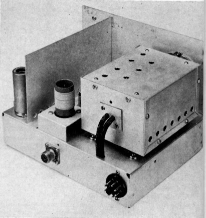
Fig. 7. Tank-enclosure mounting. The shield box is set on half-inch pillars to minimize heat conduction from the chassis to the box. Ventilating holes in the box cover are arranged so air enters at the bottom of the outer side and emerges at the top left. Note that additional sheet-metal screws are used to hold the cover firmly in place.
To shield the tank box from radiated heat a baffle plate of bright aluminum is mounted right alongside the tubes so their heat is reflected outward from the chassis. Quarter-inch holes are drilled in the chassis alongside the tube sockets and along the bottom of the baffle plate, Fig. 8, to encourage air circulation upward past the tubes. The cover and bottom plate for the entire assembly are made from open-work do-it-yourself aluminum.
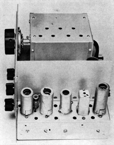
Fig. 8. Heat from the tubes causes convection currents that draw air across the chassis and through the holes in the baffle plate, as well as from below the chassis through the holes along the chassis edge.
These measures are quite effective in keeping the tank box cool. After several hours of operation the box is still just about as cool, as judged by touch, as it was before power was turned on, although the end of the chassis on which it is mounted is noticeably warm and the tube end is even more so. Actually, the measured temperature rise inside the box after a four-hour run averages 6 to 8 degrees F.
In this layout the conversion crystals at first were covered by an aluminum shield, to prevent possible stray coupling between the crystals and the output coil at the rear. This shielded space confined some of the chassis heat. Removing the shield reduced frequency drift in the crystals, and fortunately the shielding was found to be unnecessary.
Parasitic Oscillations
Lengthening the leads between the oscillator tube and the tank invites v.h.f. parasitic oscillations when a good high-transconductance triode is used. In several different physical layouts used for this oscillator parasitics invariably were generated. The frequency ranged from about 50 to 200 Mc., depending on the lead lengths. The parasitic circuit is a simple Colpitts using the interelectrode capacitances to tune the grid and plate leads, as shown in Fig. 9. The regular tank capacitors are so large that they act as a short circuit at the end of the "line" formed by the leads from the tube to the tank.
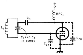
Fig. 9. Parasitic-oscillator circuit formed by leads from the grid and plate to the tank. The inductance of Li is large enough, at v.h.f., to act as an r.f. choke. Parasitic oscillations are likely to occur when the leads (drawn with heavy lines) are an inch or more long.
Various chokes and choke-resistor combinations were tried in the grid and plate leads, and although they always could be made to suppress the parasitic after a little tinkering, the choke size had to be changed with each change in lead length. It is simpler to use resistance only, but since appreciable resistance is undesirable in either lead at the fundamental oscillator frequency the lowest possible value of resistance should be used. At the fundamental, a given value will be equally bad no matter where it is placed in the lead, but fortunately this is not true at the parasitic frequency. A low resistance at a high-current point in a parasitic circuit will be equally as effective as a high resistance at a low-current point. The high-current point in this parasitic circuit is right at the tank capacitors, so the resistor should be installed there. A 10-ohm carbon resistor, R2 in Fig. 4, has been effective in several oscillator arrangements of this type.
It is more than likely that unsuspected v.h.f. parasitics exist in a great many low-frequency oscillators. The better the tube, the more likely they are to occur. Low power is no insurance against them. They cause erratic frequency changes, "hot" spots and body capacitance where there shouldn't be any, and similar effects. A rectifier-type wavemeter check should be made on any oscillator - just to be sure.
Vibration and mechanical shock
It is traditional to say that an oscillator should be "solidly constructed," and if this is interpreted to mean that the construction shouldn't be flimsy, the principle is good. "Solid," though, needs qualification. A bell is solid, but it can vibrate like mad. "Sound deadened" perhaps would be a better description of what is needed. The construction should be such that the oscillator cannot "ring" mechanically.
Since metal transmits vibration very efficiently, it is reasonable to assume that the vibration-sensitive parts should not be mounted on metal. Wood does not ring readily, but it is not a very satisfactory structural material for radio gear. The next best probably is a plastic of some sort.
Quarter-inch Plexiglas was used for mounting the tank components in the oscillator shown, and has proved quite satisfactory. Plexiglas is also an insulator for heat. It slows down the conduction of heat from the box to the tank components, contributing further to making the temperature change, and hence the drift, very slow.
The tank and plastic plate form a single unit, mechanically. This type of assembly is less susceptible to mechanical shock than chassis mounting, since any movement tends to occur as a whole, rather than as a series of separate responses. The Plexiglas plate is mounted on pillars at its four corners; a three-point mounting theoretically might be better, but was avoided here because of the possible torsion effects when turning the variable capacitor (any twisting of the assembly with tuning probably would result in backlash).
The insulating base makes it possible to avoid multiple ground paths, which often give rise to intermittent effects.(10) A single ground bus can be used; in this oscillator, it is a half-inch wide strip of aluminum running from beneath the tuning capacitor to the rear of the mounting plate. This strip is the only capacitor ground point; the rotor shaft does not touch the front of the box where it goes through, and an insulated flexible coupling is used between the shaft and tuning dial.
An "air-wound" coil such as Miniductor deserves special attention. The principal problem is the method of mounting; the coil itself, if small, will have very little inertia and little tendency to vibrate. In this case the mounting is a strip of Plexiglas of the same thickness as the coil supporting strips, filed down to make a snug fit and then cemented to opposite strips. The assembly is supported on ¾-inch ceramic pillars. Experience has shown this method to be vibration-proof.
Ordinary chassis mounting suffices for the oscillator tube, since the tube has so little direct effect on the frequency. The triode-pentode is rather free from microphonic effects (none have been observed) because of the small and light elements and the short internal supporting leads, along with very good bracing.
If coax cables are used to connect the tank to the tube it seems better not to fasten them rigidly. They should be clamped together so they will move as a unit under shock. At one time the cables shown in Fig. 10 were anchored midway along their length, but there was less frequency change with both temperature and vibration when this support was removed.
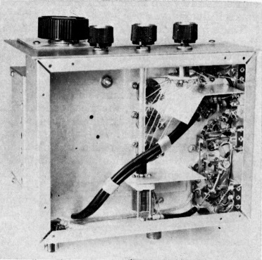
Fig. 10. The coax leads from the tank are clamped together to prevent relative movement, but are not otherwise connected mechanically with the chassis except at the ends where the electrical connections have to be made. This bottom view also shows the amplifier tuning capacitor, which is mounted on a bracket which shields it from the oscillators. The drive shaft is plastic rod.
Finally, the shield box containing the tank needs firm bonding all around the meeting surfaces of the base and cover. The box is coupled to the tank, especially to the coil, because of the electric and magnetic fields surrounding the tank components. Poor or intermittent contact between the metallic surfaces will affect the frequency in unpredictable (and usually sporadic) ways. Use enough screws so that the surfaces are everywhere firmly in contact.
With the construction shown, the oscillator frequency is completely free from any ordinary shock or vibration effects. Even dropping the entire v.f.o. on a hard table from a height of a couple of inches causes no vibration in frequency, although the shock sometimes is enough to jar the capacitor setting slightly.
The buffer amplifier
After taking the pains necessary to achieve stability in a tunable oscillator, it would be foolish to throw any of the stability away. It can happen, when the oscillator is coupled to another circuit, for the reasons stated earlier.
If the buffer is to prevent any variations that may occur either in its own plate circuit or in the following stages from affecting the oscillator frequency, its voltage amplification must be very low. This is because Miller effect(11) depends on voltage amplification. Low gain is no handicap, because in a conversion v.f.o. system the buffer should supply only a few volts of r.f. to the mixer. The buffer output circuit therefore can be simply a relatively low value of resistance - not more than 1000 ohms.
A second point is that the buffer should operate with close to its normal Class-A grid bias (obtained from a cathode resistor) and without being driven into grid current. With this type of operation the oscillator-buffer coupling can have its least value - an important factor in contributing to freedom from buffer reaction on the oscillator frequency. The buffer grid-resistor value is not too important; a 0.1-megohm resistor was used in the circuit of Fig. 11, but the resistance could be varied over a wide range without upsetting things. The coupling capacitor, C5 in Fig. 4, should have the smallest value that will result in the desired buffer output voltage; a 3.3 pF capacitor was used here.
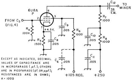
Fig. 11. Buffer circuit following tunable oscillator. Resistors are 1/2-watt composition; capacitors are disk ceramic, except C12, which is silver mica. C6 is the capacitor having the same designation shown in Fig. 4; it is unnecessary to use two separate capacitors across the same feed point. R6 and R8 are decoupling resistors backed up by C6 and C11; these circuits are essential for preventing r.f. coupling through the power-supply leads.
The presence of grid current can be detected readily with the d.c. probe of a vacuum-tube voltmeter; there should be no d.c. voltage drop across the buffer grid resistor, R4. If any such voltage can be detected in making the initial adjustments, the value of C5 should be decreased.
In general, it is advisable to operate the buffer with a small value of cathode bias and low r.f. grid voltage rather than to avoid grid current by increasing the cathode resistance. This minimizes generation of harmonics of the oscillator frequency by the buffer tube and thus helps reduce spurious output in a conversion system. Vibration and shock are minor problems in a buffer circuit of good electrical design. Ordinary construction methods suffice. The important thing in layout is to make sure that the buffer plate circuit cannot "see" the driving circuit electrically. This is readily done, in the layout shown in Fig. 12, by continuing the oscillator-tank coax shields as far as possible toward the grid and plate prongs of the tube socket, by mounting disk bypass capacitors over the socket to act as shields between the pentode plate and other elements, and by separating the "hot" components (the oscillator plate choke, RFCI, and the buffer plate load resistor, R7) as much as possible.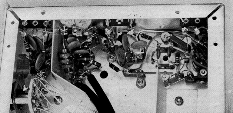
Fig. 12. A close-up of the wiring around the tunable-oscillator/buffer socket (to the right of bent shield plate) and the crystal-oscillator/buffer socket in the upper left corner. The metal center post of the socket is connected to the chassis through a soldering lug fastened under one of the socket mounting nuts; this is the single ground point for the stage. The some method of grounding is used in each stage. Disk capacitors are directly over the sockets to shield the oscillator and buffer sections from each other.
The frequency converter
Frequency conversion in a v.f.o. is much like frequency conversion in a receiver, and the same methods can be used. The dominant factor is that of maintaining isolation between the tunable oscillator, the output circuit, and the conversion oscillator. A converter tube such as the 6BE6 offers better isolation than some of the triode and pentode circuits used in receivers, especially in preventing coupling between the tunable oscillator and the fixed conversion oscillator.
Whatever the method of conversion, the fixed-frequency oscillator - usually crystal controlled - should be entirely separate from the mixer. And even though a crystal is a pretty stable device, it is advisable to follow the oscillator with a buffer amplifier. If the mixer is a 6BE6 it is preferable to let the crystal oscillator drive the injection grid, which requires some power, and to apply the tunable-oscillator/buffer output to the signal grid. Furthermore, to stay within the "linear" range of conversion the mixer tube should be operated with the same injection voltage that would be used in receiving - about 15 volts of rectified injection-grid voltage across a 22,000-ohm grid leak. The signal grid should be operated with Class-A bias and should not be driven into grid current.
The conversion oscillator
Fig. 13 is a practical circuit for the conversion oscillator and its buffer amplifier. The triode section of the 6U8A is used as a Pierce oscillator operating at low plate voltage, with light coupling to the pentode section used as a buffer amplifier. Since it is necessary to develop appreciable r.f. voltage for the 6BE6 injection grid, a tuned tank is used in the plate circuit of the pentode. If a wide range of crystal frequencies must be used for getting output in various bands, the crystals and buffer plate tanks can be simultaneously switched. The L/C ratio of the buffer tank is not too critical, but it should be low enough so that the Q will be reasonably high; the tank should contribute enough selectivity to minimize crystal-frequency harmonics.
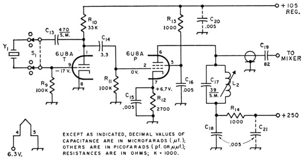
Fig. 13. Crystal-controlled conversion oscillator and buffer amplifier. Output tank capacitance includes the capacitance of the coax line between plate and C19; if this lead is more than two or three inches long the capacitance of C17 may have to be modified to compensate. C19 should be at the mixer end of the coax line. If this and the circuits of Figs. 4 and 11 use the same power supply, C20 is identical with C6 in Fig. 4 and C21 is the same capacitor as C11 in Fig. 11.
C13,C17 Silver mica.
C14,C15,C16,C18,C19,C20,C21 Disk ceramic.
L2 Slug tuned, to resonate at crystal frequency with C17 and associated stray capacitances. For crystals in the 6- to 8.5-Mc. region a coil adjustable from 6.7 to 15 µH (Miller 4406 is suitable).
R9-R14, inc.- ½ watt composition.
S1-Ceramic wafer switch; sections and positions as required. A 2-section switch with 6 positions is used in the v.f.o. pictured.
Y1-Conversion crystals, as required.
The amplitude of the r.f. voltage supplied to the injection grid can be regulated by adjustment of the slug in L2. One setting will suffice for a group of crystals in a narrow frequency range such as is used in the experimental v.f.o. In the snore usual arrangement where each amateur band has a single conversion crystal, individual coils will be needed for each band and may readily be adjusted for optimum output. Overall control of output lies in the choice of R12, lower values giving higher gain. With the circuit constants shown, the pentode is biased to about 7 volts and operates without grid current.
Stray coupling
Oscillator-to-oscillator coupling may give rise to unanticipated effects. Note that in Fig. 12 there is a shield between the sockets for the tunable-oscillator and conversion-oscillator tubes. This shield was not used at first, and there was a small amount of coupling between the two circuits. The two oscillator frequencies combined in the crystal circuit, causing a difference-frequency signal to be applied to the 6BE6 injection grid. As this signal was at the converter output frequency it was amplified and fed to the following stage. Even when negative grid bias beyond the cutoff value was applied to the 6BE6 control grid there was a weak residual output that could not be eliminated. This made it impossible to use break-in keying with complete effectiveness. Installing the shield eliminated the coupling and made the mixer behave normally.
While coupling of this type might not occur in other layouts, the possibility of its existence should be kept in mind, especially if rated cutoff bias on the signal grid of the mixer does not completely cut off the output.
The mixer plate circuit
One of the disadvantages of the conversion system is that it has innumerable by-product output frequencies, in addition to the desired frequency. If these are not suppressed they may go on through to the antenna to result in spurious radiations. The first real barrier to such frequencies is the mixer output circuit.
The mixer should not be asked to deliver power to the following stage, but only to develop enough r.f. voltage for exciting a high-gain pentode as a Class A1 or AB1 amplifier. This takes only a few volts of r.f., so the mixer plate circuit should be designed primarily for attenuation of unwanted frequencies. A double-tuned transformer is highly desirable.
If the band of desired frequencies is narrow, in terms of percentage of the center frequency of the band, a slightly overcoupled tuned transformer will give sufficient band-pass effect to make more than initial adjustment unnecessary. A separate transformer for each band can readily be switched in as required. This method is usable for bandwidths up to 4 or 5 per cent of the center frequency. Wider bands may require a ganged variable capacitor to tune the transformer - which has the incidental advantage that, since looser coupling can be used between the transformer windings than in the bandpass case, the selectivity is increased.
Single-tuned circuits with capacitive coupling to the following stage, although less desirable, are simple to design and apply. They will usually give sufficient selectivity in transmitters where at least two tuned stages follow the mixer. It does not really matter how the selectivity necessary to prevent spurious radiation is obtained so long as it is obtained.
A single fixed-tune bandpass circuit, T1 in Fig. 14, sufficed for this v.f.o. since mixer output was wanted only in the 3500-3650-kc. region. In the more usual conversion arrangement giving direct output on each band, a separate mixer output circuit would have to be provided for each.
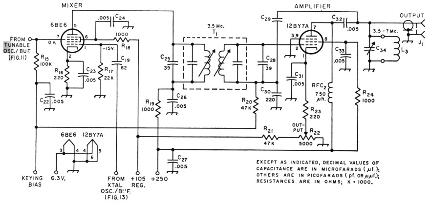
Fig. 14. Mixer and output amplifier circuit. Except for C29, all fixed capacitors are disk ceramic. Fixed resistors are ½-watt composition. C10 is the capacitor having the same designation in Fig. 13.
C29 "Gimmick" capacitor; twisted hookup wire adjusted to neutralize amplifier.
J1 Coaxial connector, chassis mounting.
C34 140 pF variable (Millen 22140).
L3 For 3-foot length of RG-62/U (app. 40 pF) cable in parallel with C341
3.5 Mc. 33 turns No. 22 enam. close-wound on 1-inch diameter plug-in form (Millen 45005).
7 Mc. 14 turns No. 22, ¾ inch long, on same type form.
R22 5000 ohm control, linear taper.
RFC2-750 µH r.f. choke (Millen 34300-750).
T1 4.5 Mc. TV sound-i.f. transformer (Miller 6270) loaded to 3.5-3.6 Mc. by C25 and C28.
The output amplifier
Up to the mixer output the overriding objective should be to get a signal that will be clean and stable under any conditions of operation, including keying in the mixer signal-grid circuit. If the v.f.o. circuits are incorporated in a complete transmitter, the rest of the design can go on from there. For a separate v.f.o. unit it is better to include an amplifier, partly for additional selectivity to discriminate against spurious output frequencies, and partly to obtain enough power output so that coupling losses and driving requirements of the transmitter can be supplied.
For highest power sensitivity a video-amplifier pentode is the most suitable tube type, and of these the 12BY7A has the lowest grid-plate capacitance, a desirable characteristic in an r.f. amplifier. However, the capacitance is not low enough to prevent self-oscillation under all conditions, especially with Class ABl operation. The amplifier should therefore be neutralized.12 This is easy to do when it is driven through adouble-tuned transformer, as shown in Fig. 14.
Since the complete v.f.o. shown here was intended as a crystal replacement, the amplifier output circuit is a parallel-tuned tank having part of its tank capacitance in a 3-foot length of ltG-62/U cable. The stage can be used either as a straight amplifier on 3.5 Mc. or as a doubler on 7 Mc. In either case there is ample output for driving the crystal-oscillator tube in practically any transmitter, since none of these operate at a power level of more than a few watts. Other types of output circuits for these frequencies could be substituted, if necessary.
For regulating the drive to the transmitter's ex-crystal-oscillator tube the amplifier has a cathode-resistor gain control, R22. The 12BY7A is grid-block keyed along with the 6BE6 mixer, to make doubly certain that there will be no "leak-through" in break-in work.
Observance of the principles discussed here has resulted in a v.f.o. in which keying has NO effect on the frequency. In fact, there is not even a phase shift in the output of either the tunable oscillator or crystal oscillator when the mixer grid is keyed, either with or without shaping.
Final note
After measurements had been made on the tunable oscillator at approximately 5 Mc., curiosity prompted replacing the tank coil with one that would let the circuit be tuned to about 2500 kc. The capacitance of C3, originally 35 pF, was increased to 50 pF and a new series of crystals in the 6-Mc. region was substituted in the conversion oscillator. Aside from the new coil and variable capacitor, no changes were made in the tunable-oscillator tank constants.
The solid curves in Fig. 15 show the maximum and minimum limits of drift measured in seven 5-hour runs. The dashed curve is a single run which approximates the median of the two limiting curves. For the 5-hour period the median drift was about 70 cycles.
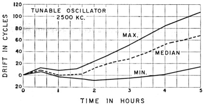
Fig. 15. Typical drift curves of tunable oscillator operating at approximately 2500 kc. These represent the extremes of performance in seven actual drift runs.
The crystals used in the conversion oscillator happened to have a positive frequency/temperature coefficient - i.e., the frequency increased with temperature. The opposite was true of the tunable oscillator. When the difference frequency is taken as output, as in this case, the two drifts add. Fig. 16 shows the results of 12-hour drift runs made on three occasions. The section to the left of the vertical dashed line covers the same length of time as Fig. 15. The effect of crystal drift is quite apparent when the two sets of curves are compared. The particular crystal used in making these runs had a total drift of 40 to 50 cycles. Most of it occurred in the first 30 minutes, after which the crystal settled down; the drift from then on was practically that of the tunable oscillator alone. The effect of crystal drift after the first half hour is to shift the tunable-oscillator drift curves upward by a fixed amount. If the crystal and tunable oscillators had both drifted in the same direction the total drift would have been their difference.
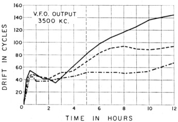
Fig. 16. Drift in output frequency over a 1 2-hour period. Comparison with Fig. 15 shows the effect of crystaloscillator drift, which was predominant during the first half hour.
Using the 2.5 Mc. tunable oscillator and 6-Mc. crystals, the output, relative to fundamental output, on frequencies other than the desired one was measured with the amplifier tuned to both 3.5 and 7 Mc. (doubling in the latter case). The approximate limit of the measuring equipment was 80 db. The measurable outputs were as follows:
With output on 3.5 Mc.:
| Freq. kc. | dB down | Remarks |
|---|---|---|
| 2550 | 65 | Tunable oscillator |
| 4450 | 75 | Beat product |
| 7000 | 19 | 2nd harmonic of output |
| 10500 | 59 | 3rd harmonic of output |
| 12100 | 72 | 2nd harmonic of crystal oscillator |
With output on 7 Mc.:
| Freq. kc. | dB down | Remarks |
|---|---|---|
| 3500 | 29 | Fundamental |
| 6050 | 59 | Crystal oscillator |
| 10500 | 42 | 3rd harmonic of 3500 kc. |
| 12100 | 65 | 2nd harmonic of crystal oscillator |
| 14000 | 65 | 2nd harmonic of output |
The only ones of importance are those that would be expected from a "conventional" v.f.o. - i.e., harmonics of the desired signal. These are generated in the output amplifier/doubler. Other spurious responses are kept to negligible amplitude by careful adjustment of the buffer and mixer operating conditions and signal levels. The spurious output rises immediately when any of these stages shows grid current.
Notes
- The pillars in the version shown are metal, but celotex insulation between the chassis and tank box also was tried. with no metal-to-metal contact. There was no observable difference between the two methods.
- Such as those described by Long in the article mentioned in footnote 7.
- Miller effect is the change in input resistance and reactance caused by feedback through the grid-plate capacitance. It depends on both the grid-plate capacitance and the actual voltage amplification, and becomes less when either is made smaller. It is the principal reason for using a pentode kith the smallest available grid-plate capacitance.
- This rule should be applied to any high-gain pentode r.f. amplifier stage. We have yet to see one that would not go into oscillation when actually tested for it - including those that supposedly "required no neutralization." The unneutralized ones either are tested only when heavily loaded, or operate as locked oscillators (or are at least highly regenerative), the instability being concealed by various means, such as keying the stage. No amplifier will oscillate with its plate current cut off; it may stay in lock with the driving source, key closed, as long as the source is operating.
George Grammer, W1DF.
Part 1 - Part 2