Loading coils for 160-meter antennas
Why waste your transmitter power in lossy loading coils? Follow these guidelines for highest efficiency in coil-loaded antennas.
One of my interests in Amateur Radio is operating with short inductive-capacitive top-loaded, ground-mounted vertical antennas on 160 meters. By short, I mean 160-meter antennas up to about 60 feet in height to the loading coil. I have given much consideration to the coils used, and to their placement in the loaded antenna.(1)
Assuming a practical limitation on how large one can make the capacitance structure above the coil, there is a restriction on the loading-coil loss. This loss restriction is a function of antenna height and ground-loss resistance. When coil losses rise above this restriction, the advantage of top loading over base loading disappears. Losses in loading coils arise from several basic sources - ac resistance of the coil windings, loss induced by surrounding structures, the effects of shunting capacitance of the supporting and surrounding structures, the inherent distributed capacitance of the coil itself, and coil-form loss.
Loss from surrounding structures is reduced by generous spacing of the coil from parts used to support it, particularly those causing shunting capacitance. Form loss and distributed capacitance are reduced by using minimal amounts of low-loss, lowdielectric-constant material for coil forms.
The ac resistance of the wire in a coil is higher than its dc resistance (excluding external inductively coupled losses). This is caused by three basic phenomena - skin effect, proximity effect and shunting capacitance, including that of the distributed capacitance of the coil itself.
Skin effect
At high frequencies, the current in a conductor confines itself to a surface layer, and the current density decreases exponentially with depth. Skin depth is that depth at which the current density is l/e, where e = 2.718281828... , that is, 37% of the surface current density. It is the depth having a resistance equal to that which would exist if the current was uniformly distributed in a conductor of that thickness.
Skin depth is a function of electrical conductivity and permittivity, magnetic permeability and curvature of the conductor, and frequency. Skin depth is less in higher conductivity and higher permeability materials and at higher frequencies. In a flat, copper conductor at 2 MHz, the skin depth is about 0.002 inch, and deepens with curvature of the surface. Hence, a straight round copper conductor has an ac resistance that depends on its diameter and the frequency. The ac resistance is some calculable function of its dc resistance. In the case of a solid wire, the ac resistance is a multiple of the wire's dc resistance. A piece of hollow tubing with walls at least five times thicker than the skin depth will behave the same as a solid wire having the same diameter as the outside-diameter of the tubing.
Copper and most other so-called nonferrous metals have essentially the permittivity of free space and no significant permeability. The conductivity of silver is about 6% higher than that of copper at dc. At radio frequencies, however, silver's performance is only about 3% better than copper's because the skin depth is a function of the square root of conductivity.
Proximity effect
When a wire is wound into a coil, the free electrons constituting the current in one turn are repelled by the free electrons in adjacent turns. The current is thus forced to portions of the wire cross section farthest away from the adjacent turns. This nonuniform distribution of current increases power loss, as power is proportional to the square of the current.
The magnetic field of each turn in a coil induces a voltage in the surface of the other turns in its proximity, and that voltage causes a current to flow. This is true for all the turns in the coil, with current flowing from the induced voltage in much the same way that the primary of a transformer induces voltage and current flows in the secondary and receives the coupled loss. These currents incur power loss, which is reflected to the coil as part of the ac resistance.
For a given inductance, coil diameter and length, there is an optimum wire diameter that balances skin and proximity effects against the resistance of the wire. Using the optimum wire size minimizes the resulting ac resistance of the coil.
Distributed capacitance
The optimum wire diameter (size) results in space-wound turns. Space between the turns also reduces the distributed capacitance of the coil below that of a close-wound coil. Such capacitance causes circulating currents to flow through the coil, incurring additional loss.
A loading-coil study
I made a study to investigate the effects of varying the coil length, diameter and wire size for several inductance values. Coil-form materials were considered and some tests were made. The sections that follow treat minimization of top-loadingcoil loss, consistent with reasonable mechanical considerations.
Based on work by Butterworth, Terman's Radio Engineer's Handbook provides means to calculate the ac resistance of single-layer coils wound with round wire of a given inductance, coil diameter, coil length, and wire diameter.(2) This permits a study such as mine to be made. Terman also provides a means for direct calculation of the optimum wire diameter. You will find the appropriate equations in the Appendix.
The ac resistance formula, Eq 4, satisfactorily compares the merit of different proposed designs, and indicates which are the most promising even under conditions where the absolute accuracy of the formula is not particularly high. Terman discusses this in essentially these words on his page 83. The technique, therefore, seems well suited to the purpose of this article.
An inductance of 150µH was selected for the study on the basis that more than 150 µH is difficult to achieve without incurring excessive coil loss in a short, toploaded antenna. Similar studies for coils of 80 to 190 µH were made and the results, although different in values of ac resistance, lead to the same conclusions.
Eq 1, used to calculate the number of turns on each coil for its optimum wire size, is based on the low-frequency inductance. However, the presence of shunting capacitive reactance, including the distributed capacitance of the coil itself, acts to increase the apparent inductive reactance and the ac resistance to higher values, depending on the total shunting capacitance and the frequency of operation. The ac-resistance multiplying factor is equal to the square of the ratio of the high-frequency inductance to the low-frequency inductance. Proof of this is left as an exercise for the reader.
Shunting capacitance, depending on the structure used, is unavoidable in antennas and is inherent in coils. The coil in this study has a low-frequency inductance of 124 µH, which is equivalent to 150 µH at 1.9 MHz with selection of an estimated typical total shunting capacitance of 10 pF. Remember, we are dealing here with a coil that can be resonated with something like 40 pF of top-loading capacitance, depending on the height to the loading coil and diameter of the mast.
Coil form diameters of 2, 4 and 6 inches with winding length-to-diameter (l/diam) - ratios of 0.5, 1, 2 and 4 were selected. A midband frequency of 1.9 MHz was used to calculate the ac resistance for wire sizes ranging from those requiring close-winding through the calculated optimum size to somewhat smaller sizes. The results are plotted in Fig 1 for the twelve coils.
Fig 1 - Curves of ac resistance versus wire gauge numbers. Coils have form diameters of 2, 4, and 6 inches, and for each diameter, lengths correspond to l/diam ratios of 0.5, 1, 2 and 4. Numbers l x diam at each curve indicate length by diameter in inches. Vertical marks at the minimum of each curve indicate the optimum wire gauge for that coil.
For plotting purposes, wire sizes larger than 0.2893-inch diameter (gauge no. 1) are identified as 0 or negative gauge numbers. Such large sizes, if used, would most likely be copper tubing, so corresponding tubing sizes (OD) are noted in Table 1. The left end of each curve in Fig 1 indicates the close-wound limiting wire size for each coil. Vertical marks at the lowest point in each curve indicate the optimum wire size for that coil. These points may fall on non-integer wire sizes, as my program treats wire size as a continuous variable.
| Tubing Size (OD) | Gauge No. |
|---|---|
| 1/8 in. | 8.25 |
| 3/16 in. | 4.76 |
| 3/8 in. | -1.21 |
Conclusions
Some conclusions may be drawn from the curves. For each coil, the minimum ac resistance occurs for a wire size of the same value as that calculated with Eq 3. Terman deems this surprisingly simple calculation quite accurate. A coil using the optimum wire size has less resistance than one close-wound with larger wire. It will also have less distributed capacitance.
Departures from the calculated optimum wire size sufficient to accommodate the usually more-available, even-numbered wire size do not have significant effect. The curves are slightly flatter to the right of the "optimum wire size" mark. This indicates that it is better to select the next smaller diameter wire (higher gauge number) when the optimum size falls between two integer wire sizes. For example, if Eq 3 yields a diameter between that of no. 9 and no. 10 wire, use no. 10, even if the calculated diameter is closer to that of no. 9. Again, for example, if the calculated wire diameter falls between that of no. 8 and no. 9, the better choice would be no. 10 if no. 9 is not available.
The broken lines showing the locus of the "optimum size" points in each diameter family flattens quite rapidly for f/diam ratios exceeding 2:1. Therefore, coils that have essentially an air core and are wound with lengths greater than twice their diameter make little sense. For a coil on a form, considering the increased quantity of material in the field of the coil for longer lengths and considering the increased distributed capacitance from the dielectric constant of the material, it is most likely that the best e/diam ratio is probably closer to 1:1. This seemingly supports one popular conception that the optimum coil is the so-called square coil, that is, a coil with a 1:1 e/diam ratio.
Contrary to the usual operation of Murphy's Law, this has the advantage of permitting larger clearances between the coil and its supporting structures for a given total form length extending beyond the winding space. Such advantages of mechanical assembly cannot be ignored. Witness the popularity of the "Minooka Special."(3) Extremely short top whips and an "interference fit" to convenient electrician's tubing are its principal virtues. Calculated ac resistances of its coils, 1.038 inches in diameter and up to 3½ feet long, run as high as 100 ohms without consideration of distributed capacitance!
It is sometimes difficult to convince a person that using a smaller wire with the same number of turns will reduce the loss compared with a coil that is close-wound with a larger wire size. If higher current-carrying capacity than that provided by the optimum wire size is required to avoid overheating, then using a larger wire size is not the answer. Making a skinny coil longer with larger wire will provide more area for heat dissipation, but will not reduce the loss. In these cases, a coil that is larger (in both diameter and length) and with a larger optimum wire size is required. An insidious aspect of QRP operation is that high losses do not reveal themselves by smoke or heat!
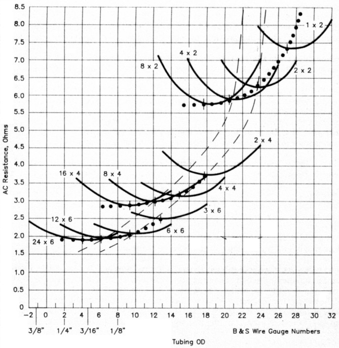
Fig 1 shows that increasing the form diameter from 2 inches to 4 inches, or possibly somewhat more, significantly reduces the ac resistance while still providing for a reasonable mechanical structure. Going to a 6-inch diameter form provides only a marginal improvement while making the mechanical construction more difficult. More weight and wind loading are added, along with the requirement for cumbersome wire sizes or copper tubing. Even if you can handle it, the bigger coil may increase the shunting-capacitance problem.
The two broken-line curves showing the locus of the optimum wire size for the 1:1 and 2:1 ratios indicate this diminishing return by flattening as the 6-inch-form coil set is approached. Coils of lower inductance values on the same size forms tend to show less of this flattening. Of course, for lower values, loss is not as much of a problem and there is less need for the larger form. The reduced separation in that region seems to indicate a lessening of the optimum f/diam ratio principle with increasing coil diameter. If coil-form loss was included in the calculation, the curve would flatten even sooner because of the increased amount of material in the field of the coil.
Coil-form considerations
Ideally, coil-form material for top-loading coils that are in a hostile outdoor environment should have low loss (dissipation factor), low dielectric constant, low water absorption, adequate mechanical strength, and the ability to tolerate heat, cold, rain, birds, and sunlight. It's easy to consult books such as Reference Data For Engineers and come up with a list of materials with names difficult to pronounce and more difficult to procure.(4) Did you ever try to buy a 20-inch length of 4.5-inch OD polyvinylcyclohexane tubing? If you could find it, have you any idea what minimum size piece you would have to buy, and just what it would cost? The same consideration applies to more well known materials such as polystyrene, Teflon™, Isolantite™, Micalex™ etc.
Dropping down to the next tier of desirability (higher dissipation factor), we come to materials such as Bakelite, polycarbonate (Lexan™), and - what's this? - 100% polyvinyl chloride. That's PVC!
Reference Data for Engineers says that 100% PVC has characteristics comparable to the others named in that second tier, except for a rather low distortion temperature of 54°C (129°F). Hmmm - PVC might not do so well with a little power loss on a 115° day here in Arizona.
But let's face it! Most loading-coil construction articles in QST call for PVC - even those by authors who will tell you how poor it is. Mention PVC on the air and you stir up a hornet's nest of controversy - most of it hearsay.
I purchased a length of 3-inch (3 /-inch OD) PVC at the local hardware store. I boiled it in water for 20 minutes, and then, while it was still hot (considerably above 129°F), I tried to distort it with pressure. I could detect no significant change in its stiffness. Perhaps hardware-store PVC is not the "100% PVC" listed in Reference Data for Engineers. Perhaps it has fillers that change its characteristics.
I wound a coil such that I could slip a piece of PVC tubing in and out of the turns. Using an RX noise bridge, I resonated the coil at 6 MHz with a mica capacitor. Placing the PVC tubing inside the coil produced only a small change in resonant frequency, expected because of the dielectric constant of the PVC. But I could detect no change in the coil's resistance at resonance (Q).
I soaked the piece of PVC tubing in water for 24 hours. After wiping and drying the surface, I repeated the experiment. Again, there was no detectable change in Q.
The dielectric constants and dissipation factors of that last tier of materials are similar. Curiously, l00% PVC is listed as having a 3-GHz dissipation factor about one third that at 1 MHz. Because power loss is proportional to frequency and dissipation factor, a test in a 2.3-GHz microwave oven should be about 500 times more stringent than a test at 2 MHz.
I placed a PVC sample in my 700-W microwave oven (with the recommended minimum load of a cup of water) and ran the oven until the water was boiling vigorously. The PVC was no warmer than the air exhausting from the oven magnetron compartment. Apparently PVC is not so bad after all. But I suggest testing a sample in a microwave oven before using it; all hardware-store PVC might not be the same.
I would not groove a PVC form. Grooving opens the surface for moisture entry and almost any varnish or coil dope will eventually crack away from the surface, allowing entry of moisture.
At least one leading antenna manufacturer uses ABS (a plastic containing styrene) as an insulator in an antenna structure under high voltage. I have always been suspicious of hardware-store ABS - that its gray or black color might be a carbon-black filler. A QSO friend building a coil pur chased similar lengths of PVC and ABS pipe at a hardware store. Following my advice, he put them in his microwave oven and ran it long enough to boil away a cur of water. The ABS got hot; the PVC did not. This does not necessarily mean that the ABS is not suitable at 2 MHz, but the PVC would seem to be better, at least pending further information.
Construction
This is not a construction article. But there are aspects of construction that affect loss. The most common construction for a loaded antenna is to mount the coil form (preferably on a removable section) at the top of the mast, and mount the capacitance structure on top of the coil form so thL masts are coaxial. One method puts bell in the coil-form ends. In this case, make the form long enough so the metallic end bells are at least a coil diameter away from the ends of the coil. Otherwise they act as a shorted turn, inducing loss resistance into the coil and lowering its inductive reactance. Ferrous metallic end bells are worse: they introduce even more loss, as in general they are more lossy.
The second configuration splices the up per mast to the lower mast with either ar insulating rod inside the masts or insulating tubing outside the masts. Hardware thee secures the coil form around the insulating rod or tube. In this case, the form shoudc: be long enough so the mast ends are at lease a coil diameter away from the winding ends. Threaded rod or bolts used to mourn the form should be at least a coil diameter away from the coil ends. This require either that the form be quite long or else the bolts securing the mast ends to the in sulating rod or tube be separate from those mounting the coil form.
A somewhat shorter coil form can be used with the spliced masts by offsetting the coil and mounting it sufficiently fa: from the mast splice by threaded rod tha enters only one side of the coil form. In nc case should the mounting hardware at boll ends of the form be connected to the sam( mast. The voltage across the loading coi can be quite high. Over a modest grounc and with 100 W to a 40-foot antenna, there is about 3 kV RMS across a 150-µH coil over a good ground system, 4.5 kV, and with 1500 W, about 16 kV. The splicing roc or tube and the coil form must withstanc this voltage.
The ends of top-loading capacitance structures should be smooth or balled t0 reduce the chances of corona discharge Spiders, discs, and other horizontal elements, such as crossbars, have a greater capacitance to the mast below the coil thar vertical members such as whips, so they should be somewhat above the coil if they're large. A small spider (perhaps tree 9-inch-long, half-inch-wide flat-aluminun legs) close above the coil sometimes make: a convenient fine-tuning control with only a tiny concession to shunt capacitance.
Attach guys to the mast with insulators. Otherwise, their capacitance to the top-loading capacitance structure shunts the coil. Currents flowing downward from the mast in uninsulated guys steal current, and because this current flows counter to the mast current, radiation resistance and efficiency are reduced. Guys above the coil are impractical because ordinary strain insulators cannot take the voltage present there.
Use brass machine screws, nuts and lock washers to secure the winding ends to the form. Leave pigtails of the winding to make connections to the mast below the coil and to the capacitance structure above the coil. Solder ring terminals to the pigtails, and secure them to the masts with self-tapping screws and star washers that dig in and make a good air-tight connection. Do not terminate the coil windings at the brass screws on the coil form; this requires another potentially lossy joint at each end of the coil.
Winding the coil
I have a novel means of winding a tight coil on PVC. Drill the form at the winding-end points and install brass machine screws with brass nuts and lock washers. Put the screw heads inside the form. Secure the far end of the wire to a wall, fence, or vise. Bend the near end of the wire around a screw on the coil form, in a tight U shape, over a brass flat washer. Do not cross the wire, and leave a generous pigtail. Secure the U with another brass flat washer, lock washer and nut. Tuck the pigtail inside the form. Check for clearance between the flat washers and the first turn. If necessary, add an extra nut to be sure the flat washers will not short to the first turn.
Keeping the wire tensioned, turn the form as you walk toward the anchored end. When the required number of turns are on the form, wrap the wire around the other screw just enough to keep it from slipping off. Cut the wire, leaving a generous pigtail.
Place the wound form in the freezer for a couple of hours. The coefficient of expansion/contraction of the PVC exceeds that of copper, so the winding will be looser than it was at room temperature. Working quickly so as to not allow the PVC form to come up to temperature, work the loose turns toward the loosely secured end of the coil, adjusting the spacing reasonably uniformly. The heat from your hands will warm the copper and help it expand.
Do not try to finish this process in one pass. The PVC may warm up too much. Take up the slack at the end and again secure the wire to the screw with a partial turn around it. Put the coil back in the freezer for another couple of hours and then repeat the process, spacing the turns uniformly and taking up more slack. Bend the wire around the screw in a tight U- shaped loop over a brass washer, and secure it with another brass washer, lock washer and nut. When the form comes up to room temperature, it will take a screwdriver to move the turns. They seem to squeeze so tightly that I suspect they dent the PVC.
Although the coil is tight, after extremes of temperature cycling the soft-drawn copper may no longer be as tight. (Do not use hard-drawn copper; its conductivity is only 95% of that of the soft-drawn variety.) I suggest a coat of Q Dope to ensure preservation of the spacing. The Q Dope™ can be purchased or can be made by dissolving polystyrene shavings in carbon tetrachloride. Be careful - "carbon tet" is a suspected carcinogen that affects the liver and kidneys when inhaled or absorbed through the skin!
Appendix
This appendix lists the equations used in the coil study. Parenthetical notations indicate page references in Terman.(2)
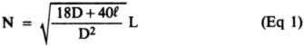
Turns required for selected inductance (Eq 37, p 55, rearranged):
where
D = diameter of coil, inches
f = length of coil, inches
L = low-frequency inductance of coil, microhenries
Maximum wire diameter for given coil length:
![]()
where
dm = maximum wire diameter, inches
f = length of coil, inches
N = number of turns
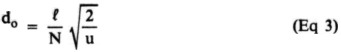
Calculation of optimum wire diameter (Eq 100, p 83, and Table 19, p 78):
where
do = optimum diameter of wire, inches
f = length of coil, inches
N = number of turns
u = a factor depending on the coil
f/diam ratio, from Table 2
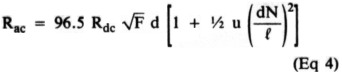
Calculation of ac-resistance factor for round copper wire, adapted for inches, and where Ter-man's c = f/diam (Eq 93a, p 80):
where
Rac = ac resistance
Rdc = dc resistance of coil (see Eq 5)
F = frequency, MHz
N = number of turns
f = length of coil, inches
d = diameter of wire, inches
u = a factor depending on the coil f/diam ratio, from Table 2
| l / diam | u |
|---|---|
| 0.5 | 4.29 |
| 1.0 | 5.29 |
| 2.0 | 6.58 |
| 4.0 | 7.74 |
See Terman (page references in parenthetical note of Eq 3) for values outside this l/diam range.
Calculation of dc resistance of coil:
![]()
where
Rdc = dc resistance of coil, ohms
D = diameter of coil, inches
N = number of turns
R1000 = resistance in ohms per 1000 feet (as is generally given in wire tables)
Notes
- C. J. Michaels, "Evolution of the Short Top-Loaded Vertical," QST, Mar 1990, pp 26-30.
- F. E. Terman, Radio Engineer's Handbook, 1st ed (New York and London: McGraw-Hill Book Co Inc, 1943), pp 77-83.
- B. Boothe, "The Minooka Special," QST, Dec 1974, pp 15-19, 28.
- E. C. Jordan, Ed., Reference Data for Engineers: Radio, Electronics, Computer, and Communications, 7th ed (Indianapolis Howard W. Sams & Co, Inc, 1985).
W7XC, Charles J. Michaels.