Practical battery-back-up power for amateur radio stations 2
Obtaining and installing a back-up battery is the first step toward assembling your own back-up-power system. Next, you've got to charge that battery - and keep it charged.
Acquiring a float-service battery is only half of the process of putting your Amateur Radio station on back-up power. The other half is keeping the battery fully charged at all times without overcharging it. Float-service batteries are intended to be connected to their charging system continuously, except during power failures. Recharging energy can come from almost any source of electricity that provides dc.
Chargers
In an automobile, an alternator begins supplying current to the battery as soon as the engine starts. Occasionally, an automotive battery must be recharged by putting it on a charger for a few hours, letting unfiltered dc - merely rectified commercialpower-line ac, do the job with questionable current and voltage limiting. Whatever you do, don't rely on an automotive charger to maintain back-up cells and batteries. Although temporary use of such a charger to restore a depleted back-up battery is acceptable in an emergency, an automotive recharger will overcharge, and likely damage, a back-up battery designed for float service.
The best charger for Amateur Radio float systems is an ordinary, stiffly regulated 12- to 13.8-V power supply capable of sourcing 15 A or more. A home-built supply is fine, or you can use the supply that powers your existing 12-V MF/HF transceiver.(9) Ideally, the charging power supply should be capable of handling the entire system load without assistance from the battery, and the battery should be able to power the entire system without help from the power supply. See the sidebar "A Closer Look at Charger Capacity" for more on choosing the right power supply for the job.
Many off-the-shelf commercial regulated power supplies work well as float service chargers, so this article will not discuss building a charger. The standard 18- or 20-A supply usually required by a 100-wattoutput transceiver needs only a minor modification or two as discussed in the sidebar "Protecting the Charger When Commercial AC Power Fails."
Charging rate
When charging voltage is applied to a depleted battery, the initial current drain is quite heavy. How much current flows depends on the battery's terminal voltage and the charging voltage applied. The greater the difference between the charger-output and battery voltages, the greater the charging current.
As the battery charges, its terminal voltage rises. The effect of this depends on the charger in use. Nickel-cadmium batteries, for example, are usually charged by constant-current power supplies that let the applied charging voltage rise as the battery's demand falls.
Lead-acid batteries, however, prefer to be charged by constant-voltage chargers - and the output voltage of the stiffly regulated power supplies commonly used with 100-W transceivers is constant. Sourced by such a supply, a charging voltage of 13.5, applied to a battery with a terminal voltage of 11 (fully discharged), causes an initial charging current of 1 to 30 A or more, depending on the battery's capacity.
If the charging voltage is maintained at 13.5 for several hours, the charging current slowly decreases as the battery's terminal voltage rises to meet the charging voltage. If the charging voltage is held constant for a long period of time - days or weeks - the charging current gradually tapers to whatever the battery requires to maintain itself in good health. This is the float current. This tapering effect complicates calculating the time required to bring a battery back to full charge.
The time required for a full recharge can be estimated, however. As a general rule, you must restore at least as much energy to the battery as you've drawn. If, for instance, you've drawn 5 A from the battery for 5 hours, you have depleted the battery's capacity by 5 A × 5 h, or 25 Ah. This is how much capacity you must restore. You can do this at the rate of 10 A for 2.5 hours 2.5 A for 10 hours, or any combination of rate and time that equates to 25 Ah. Recharging is not 100% efficient, however, so you must increase this figure somewhat. As a rule of thumb, recharge requires about 140% of the ampere-hours you deplete - in this case, 35 Ah to restore 25 Ah. A constant-voltage charger eliminates the need for calculation: Just set the charging voltage and let the regulated power supply do its thing.
Stiff charge-voltage regulation - and setting the charging voltage accurately in the first place - is important for another reason: Float current rises very steeply with small float-voltage increases. For a string of six cells, for instance, charging current about doubles for every 0.06 V increase in charging voltage. This overcharging increases the rate at which the battery loses electrolyte and, if allowed to continue for a long period, shortens cell life. Mild undercharging is not harmful; it merely reduces the total amount of energy that can be taken from the battery before full discharge occurs, and increases the frequency with which equalizing charges(10) must be applied.
A closer look at charger capacity
A float-system charger should be adjusted to provide just enough charging current to replace the battery's internal losses. Typically, this amounts to about 1 mA per ampere-hour of battery capacity. Thus, a 100-Ah battery typically requires about 100 mA of float current at room temperature. (The required charging current increases with temperature, as discussed in the text.)
This doesn't mean you can use a 1-A float supply to keep a 1000-Ah battery topped off! Remember, the ideal power supply/charger should be able to handle the entire system load without aid from the battery (you can fudge on this just a little; see below). Of course, the system battery should be able to handle the entire load without aid from the power supply.
If you're running, say, a 100-W transceiver, a 25-W 2-meter rig, a desk lamp, a small 12-V fan and a few other accessories from your dc line you might pull a maximum load of about 30 to 35 A at 13.5 V, it all of your back-up-powered transmitters are keyed simultaneously at full power.
Because all of your transmitters operate key-down simultaneously only rarely - and, if at all, for only a few seconds at a time - you can expect a normal momentary maximum load of, say, 25 A. A 20-A continuous-duty supply should handle this nicely, with the battery handling the small momentary overload.
That said, however, resist the temptation to try to get away with a lower-capacity supply - say, a 10-A unit. Without the battery, it can't handle the system's normal peak load. Even a 15-A supply is marginal at best, because recharging a deeply discharged battery - likely necessary after a lengthy commercial-power failure - may strain even a 15-A supply because of the heavy initial current needed to charge the battery. - W4MLE
Protecting the charger when commercial AC power fails
A back-up system is intended to take over when commercial electricity fails. When the lights go out, your back-up battery continues to apply about 12.5 V dc to the output connectors of your power supply - and to the output terminals of the regulator IC in that supply. At the same time, the absence of commercial ac reduces the regulator's input voltage to zero. Most voltage-regulator chips deeply resent this reverse-voltage condition and respond by committing suicide. Simple cures are readily applied. Which cure you use depends on which voltage-regulator IC your supply uses. Most regulated power supplies use either a 723 regulator - a 14-pin DIP IC in Its most common form - or a three-terminal regulator, such as an LM317 (adjustable output) or one of the 7800-series (fixed output) ICs.
Protecting 723 regulator ICs
Most commercial supplies, such as those in the popular Astron series, are based on the 723 regulator IC. The 723 fails under reverse-voltage conditions because 0 V at the chip's V + pin causes too much current to be forced through the base-emitter junction of Q12, the 723's inverting-input transistor.(a) A solution, devised by Ted Zateslo, W1XO, involves installing a resistor in the base lead of Q12 (that is, between pin 4 of a 14-pin-DIP 723 and its associated components). This pin is connected to the voltage-adjustmentcontrol wiper in Astron supplies (and probably many others); you need only lift the control's wiper lead and insert the resistor - a 6.8- to 10-kΩ, 1/4-W unit is sufficient; the exact value is not critical. The resistor protects the 723 by limiting Q12's forward base-emitter current to a safe value.
One other quirk of 723 regulators comes to light less often, but has the same cause. The problem arises when a power supply has been unpowered and disconnected for some time, allowing its filter capacitor(s) to discharge completely. If the power supply is connected to the battery before being turned on, the filter capacitor tries to charge through the base junctions of Q12 and Q14. Since uncharged capacitors act as momentary short circuits, the instantaneous current can be quite large, resulting in destruction of the 723, even with the 6.8- to 10-kΩ series resistor in place.
The cure is simple: Turn on the power supply before attaching the battery. This allows the rectifier to charge the supply's filter capacitor.
Protecting three-terminal regulators
Three-terminal regulators are even simpler to protect. Connect a 1-A silicon diode, such as a 1N4004, between the IC's win and output pins, with the diode's cathode (banded end) to the INPUT pin. As long as the regulator's input-to-output differential exceeds the diode's contact potential (0.7 V or so) - no current flows through the diode because it is reverse-biased. But when the regulator input voltage drops during a commercial-ac-power failure, and the system battery keeps the regulator output voltage higher than the regulator input voltage, the diode conducts strongly, virtually short-circuiting the regulator IC and protecting its innards.
Watch out for crowbars
Crowbar circuitry protects a power supply's load from overvoltage by blowing a fuse. Usually, a crowbar consists of an SCR connected across the supply's OUTPUT terminals, and trigger circuitry set to fire (turn on) the SCR if the supply voltage exceeds a predetermined value. When the SCR fires, it shorts the supply's OUTPUT terminals and blows the supply's ac-line fuse.
Snag: A battery connected across the supply's OUTPUT terminals may dump hundreds of amperes into the fired SCR. Unless a fuse is interposed between the battery and SCR, the results tend to be spectacular! The wires between supply and battery heat quickly, often setting fire to their insulation. Unless the wires melt through, the battery electrolyte may boil, and the battery may explode.
Crowbar-caused system meltdown can be avoided by (1) disconnecting the crowbar circuitry entirely or (2) by installing a fuse between the battery and power supply in addition to the fuse already present between the battery and its load.
Solution 1 is acceptable because the battery itself clamps the supply's output voltage to a value that may not damage your gear. Warning: This overcharges the battery, and prolonged operation under this condition may damage your gear or your battery, or both. Don't substitute the battery's clamping ability for power-supply repair!
Solution 2 requires a power-supply-to-battery fuse with the same current rating as F1 in Fig 2 (in Part 1 of this series). Be sure to connect the fuse between the supply and the battery, not between the battery and its load. (Your system should already include a battery-to-load fuse [F1, as mentioned above].) The resistance of another battery-to-load fuse may noticeably degrade system voltage regulation. - W4MLE
Adjusting the charger voltage
The optimum float voltage varies with battery type, and different manufacturers of a given type may recommend slightly different float voltages for their batteries. As a general rule, however, set the power-supply voltage initially at 13.50 for lead-calcium cells, 12.96 for lead-antimony float cells, and 13.80 for deep-cycle marine and RV batteries. If necessary, cells of various types can be mixed or matched in float service, although it's better not to do so. If you do this, set your power supply to the float voltage suitable for the lowest-rated cells. For example, charge a mixture of lead-calcium float cells (13.5 V) and RV batteries (13.8 V) at 13.5 V. A mixture of RV and industrial deep-cycle batteries should be floated at 12.96 V.
After a deep discharge - as can occur when a battery provides back-up power during a commercial-ac-power failure - a high-capacity battery may draw a charging current higher than the charger can supply at the optimum charging voltage. In such a case, you can protect the supply by limiting the charging current with a series resistor, or by setting the supply's current-limiting circuitry - if the supply has it - to limit at a suitable level. If only the initial charging current is excessive, reduce the supply's output voltage until the current falls to a manageable level, then gradually raise the voltage to the float value as the battery charges and draws less charging current.
Alternative charge sources
The commercial ac power line Is certainly not the only source that can be used to charge a battery. Alternatives include automotive alternators and generators driven by windmills, water wheels or pedal cranks; 120-V ac gasoline generators; solar panels; other batteries and just about any energy source that can produce 14 to 15 V dc at more than a few hundred milliamperes. The purity of the direct current applied to a back-up battery is immaterial; the battery itself functions as a huge capacitor, swamping ripple and producing pure dc.
The alternator mounted in the family chariot can quite effectively recharge a depleted battery when necessary; after all, that's what such alternators are intended to do. Be wary, however: Like an automotive-battery charger, an automotive alternator can quickly overcharge a float battery.
An automotive alternator can be driven by a lawn-mower engine quite effectively. If the engine shaft is vertical, as is true of moat lawn-mower engines, the necessary pulleys and belt can be mounted below the platform that supports the engine and alternator. Or, a small engine with a horizontal shaft can be mounted atop the platform.
The battery must energize the alternator's field coil; the alternator's output voltage depends on how much current flows in the field coil. The field-coil current can be set by a resistor or rheostat in series with the battery, or by an adjustable three-terminal regulator IC powered by the battery. Even a heavily-loaded alternator should not require more than a few amperes of field current. Any regulator circuit designed to be driven by a bridge rectifier should work well as a field-current regulator. In this case, however, the system battery, connected in parallel with the rectified alternator output, drives the regulator (Fig A). The regulator output, adjustable from 1.4 V up to nearly the battery voltage, feeds the field winding.
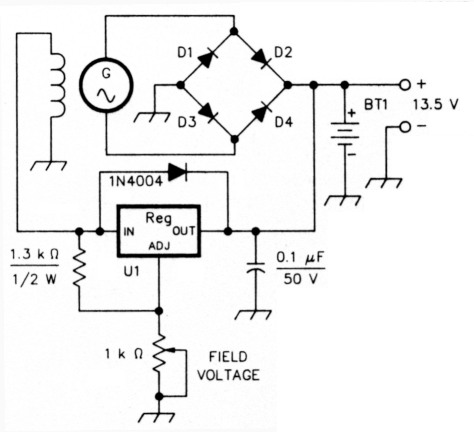
Fig A - Field control for a back-up-battery-powered alternator by means of an adjustable three-terminal regulator (U1). BT1 is the back-up battery; D1-D4 are diodes, or a bridge rectifier, capable of handling the system current; U1 is an LM317T (field currents up to 1.5 A), LM350 (3 A), or LM338 (5 A).
Many portable gasoline generators, like those used on Field Day, also have 12-V dc outputs for charging batteries, though the current-handling capacity of these may be less than that necessary for maintaining a back-up-battery system.
Of course, an ac-powered 13.5-V-dc supply can be powered by a 120-V ac gasoline generator.
Various mechanical contrivances can use the energy of the wind or a waterwheel to rotate an alternator. Articles describing such systems have appeared in Amateur Radio literature over the years.
Solar cells, an increasingly important source of altematiltp energy, come down in cost as photovoltaic technology improves and the market expands. A system using solar panels to charge batteries was described by Mideke in a two-part QST series in 1987. The Bibliography (to appear at the conclusion of Part 3 of this series) points the way to this and other sources of information on back-up-battery topics. - W4MLE
The float-current/temperature connection
Float current varies dramatically with temperature. The current through a fully charged battery nearly doubles for each 15 °F increase in electrolyte temperature.(11)
At room temperature, a battery requires about 1 mA of float current per rated ampere-hour of capacity. Thus, a room- temperature string of six 300-Ah cells would probably take a float current of about 300 mA.
If your battery is located outdoors, temperature-related float-current variations will be very noticeable on your system current monitor, with summertime float currents being much higher than those in the winter. The stiff regulation of the system charger automatically takes care of these changes without help from you. A back-up-battery system takes anywhere from several days to a couple of weeks to stabilize at a given temperature.
Equalizing charge
After a battery has been in use for some time, especially if it is often subjected to shallow discharges, its cells may tend to develop small differences in voltage and specific gravity. (Such differences also occur when the average system charging voltage is too low, resulting in chronic undercharging. This can occur if the system voltmeter is miscalibrated to indicate higher-than-actual float voltage.) An affected battery can be rejuvenated by means of an equalizing charge.
Lead-calcium batteries generally don't require equalizing very often, but lead-antimony cells may need an equalizing charge every three months, or even more frequently. The need for equalization is indicated when the cell voltage falls more than 0.04 V below the float voltage.
To calculate the nominal float voltage per cell in a given battery, divide the float voltage by the number of cells. For example, in a series battery of lead-calcium cells floated at 13.5 V, the voltage across each cell should be 2.25. If the voltage across one or more of the cells in such a battery is 2.21 or less, an equalizing charge should be applied. To do this, raise the float voltage to about 2.4 per cell (14.4 V for a battery of six cells).
This raises the string's charging current dramatically. Maintain the equalizing charge until all the string's cells test at almost the same voltage - less than 0.04 V difference between the highest- and lowest-voltage cells in the string. Then, reduce the float voltage to its normal 13.5.
For lead-antimony float batteries, apply 13.98 V to equalize a string of six cells. The cells should equalize at around 2.33 V per cell after 8 to 24 hours. Then reduce the charging voltage to the normal 12.96.(12)
A battery can be recharged at the equalizing voltage provided your charger can supply the current; this is especially useful after the deep discharge that long power failures can cause. Be sure to readjust the charger to the proper float voltage as soon as the charge is restored and equalization is complete.
Back-up-battery care
Lead-acid back-up batteries require some care: they are not black boxes. Here are the basics.
Disconnected from its charger, a single float-service, lead-calcium cell produces about 2.05 V at full charge. Such a cell is considered to be completely discharged when its terminal voltage falls to 1.8 (10.8 for a battery of six cells).(13) Further discharging can damage the cell. At full charge, and disconnected from its charger, a "12-V" lead-calcium float battery (six cells in series) exhibits an open-circuit voltage of about 12.3. By comparison, the open-circuit voltage of a fully-charged car battery is about 12.6.
Back-up-battery electrolyte must be kept at the proper level by adding distilled water to replace that slowly lost by electrical decomposition (electrolysis) during charging. Keep the electrolyte somewhere between the top and bottom lines marked on the cell cases for that purpose. Never let it fall below the tops of the cell plates.
Discharged batteries should be recharged as soon as possible. The C&D manual says:
Both lead-antimony and lead-calcium batteries should be recharged as quickly as practical following an emergency discharge.... This can be done by raising the bus voltage to the maximum allowed by the other circuit components, but not to exceed the values listed.... If charging at equalize voltage is impractical, recharge at float voltage.
If a discharged battery is allowed to stand, it becomes "sulfated" and harder to recharge to normal capacity. Sulfation occurs when the finely-divided lead sulfate formed on the cell plates during discharge changes its crystalline structure to a form that resists recharging.
Disconnected from the charging system, fully charged cells can last several months before going back on charge. Backup-battery manufacturers generally recommend leaving lead-calcium cells off their float supply for no more than six months at a time without a restorative charge. Lead-antimony cells must be recharged at least twice that often.
In Part 3, the conclusion of this series, we'll discuss back-up-battery monitoring, maintenance and safety, and how to safely and responsibly dispose of unusable batteries.
Notes
- Even well-regulated power supplies tend to change voltage just a bit when the load or the power-line voltage changes, so it's a good idea to make the output voltage adjustable within narrow limits. Most commercial supplies allow such adjustment. Those that don't can usually be modified to allow it. (Caution: If you raise the output voltage of a 7800-series regulator by lifting its ADJUST pin above common, do so with a resistor, not a diode or diodes. Diodes placed between ADJUST and common can cause three-terminal regulators to fail. A 500-Ω pot, inserted between ADJUST and common on a 7812, and connected as a rheostat, usually provides an output-voltage of 12 to 14 or so. The output voltage increases as the inserted resistance increases.
- An equalizing charge is a charge applied at a voltage higher than the optimum float-charge value. This is usually done to correct cell-to-cell variations in voltage and specific gravity, as described later.
- R, Smeaton, Ed., Switchgear and Control Handbook (New York: McGraw-Hill, 1977).
- See Note 7.
- See Note 7.
W4MLE, George L. Thurston III.