The Warbler; a simple PSK31 transceiver for 80 meters
Small and inexpensive, this transceiver is packed with fun!
There's no doubt that PSK31 has taken the Amateur Radio community by storm! In fact, tidal wave might be a more fitting description! In this Internet age, the enjoyment and satisfaction of using your computer and an HF transceiver to communicate using this reliable and low-bandwidth digital mode goes beyond words. PSK31 has been rekindling the interest and excitement in hams of all ages, and is drawing new amateurs into the ranks because of its simplicity and the appeal of modern technology. Now, the low-cost entry and high success rate for those trying PSK31 for the first time has been enhanced by Dave (NN1G) Benson's inexpensive PSK31-ready transceivers, the latest of which is described here. (1)(2) When used in conjunction with innovative PC software such as DigiPan, hams can have solid contacts on any HF band.(3)
Even more astounding, PSK31 seems to be providing the means for a rebirth of an old way of communicating for us hams. We're not refering to the data modulation/demodulation techniques of SSB. Nor are we alluding to this mode's ability to pack dozens of active QSOs simultaneously into the same bandwidth as a single SSB QSO. What we're talking about is the real use of the spectrum. PSK31 is eAsA sang a way for hams of all ages to gather with record ease and efficiency around new watering holes to communicate as friends and club members.
Warbler opens 80 meters to lowcost PSK31
The PSK-80 is the newest PSK-capable trnaceiver design of Dave Benson, NN1G. The New Jersey QRP Club, whose members are kitting the rig, dubbed it the "Warbler." This very low cost 80-meter transceiver provides a way for friends, club members, schoolmates and ham relatives located within a 200 mile (or greater) radius to have solid, enjoyable, lively contacts on a regular basis. The natural propagation characteristics of 80 meters offers PSKers a way to have regular roundtable QSOs and club get-togethers on the air during the evening hours. You've probably heard of (and may have participated in) CW or SSB nets for traffic handling, weather tracking, used-equipment auctions and so on. The same net activities are now taking place using PSK31, building on the same strengths of this digital mode.
Pockets of 80-meter PSK31 activity have been springing up with increasing frequency throughout the country, due in great part to the popularity of the Warbler. Hams in Denver led by Rod Cerkoney, NORC, have started some Rocky Mountain Warbler group-build sessions to help others get on the air with this mode. QRPers in northern California, led by Bill Jones, KD7S, and Doug Hendricks, K16DS, started a Sunday evening weekly "ragchew" session called the Western Warbliers. New Jersey QRPers are on the air nightly with their Warblers and every Sunday night with a club meeting. QRPers in Atlanta are starting their own group-build of the 80-meter kit. Veteran PSKer Ken Hopper, N9VV, in Chicago, is one of the biggest on-the-air promoters of PSK3 1. We, the authors of this article, can be found most evenings operating around 3580.5 kHz.
Warbler activity
The map in Figure I shows the distribution of current 80-meter Warbler PSK31 activity throughout the country. The red circles indicate a 200-mile radius of solid contacts. As you can see, strong areas of PSK31 activity are in northern California, the Northeast, Chicago and Atlanta. Canada is also quickly coming on as a strong PSK31 player on 80 meters. The areas of heaviest overlap offer the highest density of PSK31 activity, hence the greatest possibility of success for newcomers to this mode. We know that there's been some success in attracting new blood to HF: Marc Ziegler, W6ZZZ, of Los Gatos, California, reported making his first-ever HF contact using a Warbler! The 200-mile radius of solid copy 80-meter propagation, though, gets bigger during the winter months. KD7S in northern California has reported increasingly better contacts with Derry, VE7QK, of BC, Canada. Phil Wheeler, W70X, in California, has been in regular contact with a station in Utah. Doug Hendricks, KI6DS, in Dos Palos, California, and coleader of the immensely popular NorCal QRP Club, reports "I worked Bill, KD7S, in Sanger; Dave, AB5PC, in Fresno; Ben, NW7DX, near Seattle, and Ron, K7UV, in Brigham City, Utah." Phil, W70X, in Los Angeles, reports partial copy (including a complete call sign) of NN1G's signal from Connecticut. Although the map represents only 80-meter PSK activity with the Warbler, there is an increasing amount of non Warbler PSK31 activity springing up as well. It seems that many PSK31 operators using other hardware and software equipment up on the higher bands are moving down to play with the Warblers on 80 meters. These higher-band PSKers are seeing the proliferation of Warblers as fertile new territory for ragchews, contests, experiments and propagation-favorable local communications. At any given time during the evening, we see QSOs in progress outside the Warbler passband, showing us that Warblers are facilitating a growth in 80-meter activity.
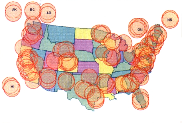
Figure 1-Geographic distribution of PSK-80
Warblers in US and Canada. Each red circle identifies three Warblers within a 200-mile solid copy area for each Warbler location. At the time this article was prepared, the current Warbler population was estimated at 500 and growing.
Local communication opens again!
Remember when you had to go to your monthly radio club meeting to hear all the latest info about new rigs, swap meets and things? The Internet now supplants a lot that need, but the scale is so wide that you might as easily chat with someone in Spain about some parts you need, as opposed to someone in the next town. In some cases, this is fine, but the camaraderie of local club members can better beachieved through PSK3 I's local communications capabilities, and that's just what many folks are doing!
Perhaps leading the pack are the Western Warbliers in California. This group had a head start because kits were first distributed at a symposium hosted by the NorCal QRP club in October 2000. These operators are maximizing that 200-mile radius of solid communications to help bring others into the fold, to help find parts and just have some regular ragchews at QRP levels. They're contributing application notes, tips, techniques and circuit improvements for other PSKers around the country. The Internet, of course, has enabled this sharing of information, and these notes are maintained by the New Jersey QRP at their project Web site.(4)
Along with the Western Warbliers, the New Jersey QRP club members have shown that it doesn't take a full-blown 80 meter antenna farm to get out with this mode. Sure, "the bigger the better" usually applies, but reduced-size antennas can put you on 80 meters without requiring an acre-size backyard!(5) The commecially available verticals also combine effective operation with a low footprint. Dave, NN I G, uses a dipole about 15 feet high for all the 80-meter PSK work he's done to date. Not bad!
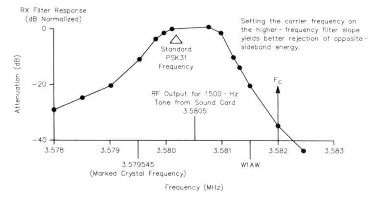
Figure 2 -Crystal-filter passband response.
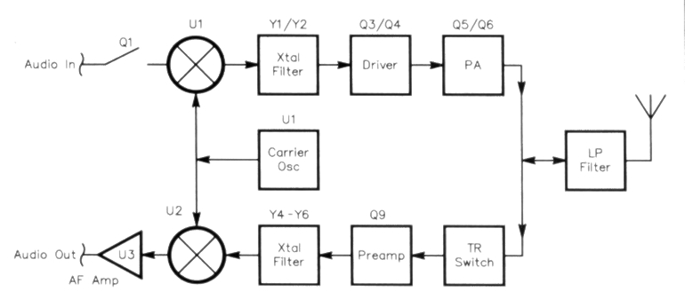
Figure 3 - Block diagram of the Warbler D-C transceiver.
So, what's a Warbler?
Last winter, while preparing for a talk on PSK31, Dave was casting about for a low-parts-count means of handling a PSK31 signal. He noted that the PSK31 watering-hole frequency on 80 meters is at 3580.15 kHz, darn close to the color-burst frequency of 3579.545 kHz. After an intensive thirty minutes of cut-and-paste engineering, a schematic was born. Remarkably, this early schematic withstood further evaluations and refinements without much growth in the parts count. The hardware design started with an evaluation of simple filters using color-burst crystals. Figure 2 shows an example of a three-crystal filter and its measured passband response.
The asymmetric skirt response is typical of a crystal ladder (Cohn) filter-the upper-frequency slope is steeper. We take advantage of this by setting the carrier/ BFO on the high side of the passband. This yields better rejection of WIAW signals and results in LSB operation. The filter uses series-resonant crystals. As a result, the passband is actually above the marked crystal frequency. The BFO is pulled to the high side of the passband using a small value of capacitance in series with the BFO crystal. So what do we do with a filter that works right at the operating frequency? Consider the Neophyte direct- conversion (D-C) receiver,(6) the epitome of simplicity: It consists of nothing more than a product detector/oscillator and an AF amp. Add a crystal filter to its front end, and it's still a D-C receiver, but its selectivity and its resistance to (out-of-pass-band) intermodulation distortion (IMD) are considerably improved. On transmit, adding such a filter to the output of a balanced modulator alters its output from a DSB signal to an SS13 signal-right at the operating frequency. A block diagram of such a setup is shown in Figure 3. Pretty simple, eh? Naturally, reducing this simplicity to practice always seems to involve adding a few components, but it's still a D-C transceiver.
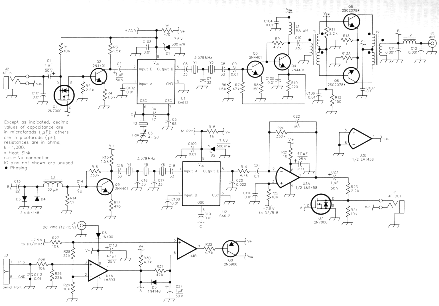
Figure 4 - Schematic of the Warbler 80 meter D-C transceiver.
Unless otherwise specified, resistors are 1/4-W, 5%-tolerance carbon-composition or metal-film units.
C1, C2, C23, C24 - 1 µF, 50 V electrolytic,
radial leads
C3, C4 - 20 pF trimmer
C4 - 47 pF disc, 5% NP0
C5 - 68 pF disc, 5% NP0
C6 - C8, C15 - Cl8 - 33 pF disc, 5% NP0
C9, C14, C101 - C106, C108 - C110, C112 - 0.01 µF disc
C10 - 330 pF disc
C11, C12 - 1 nF NP0
C13 - 100 pF disc ceramic 5%
C20 - 22 nF monolithic
C21, C107 - 100 nF monolithic
C22 - 150 pF disc
C111, C113 - 47 µF, 25 V electrolytic, radial leads
D1, D2 - 7.5 V, 500 mW Zener, 1 N5236B
D3 - D5 -1N4148
D6 - 1N4001
J1, J2 - 3.5-mm 3-circult jack, PC board mount
J3 - DB9, PC board mount 4)
J4 - DC power jack, 2.1 x 5.5 mm board mount
J5 - BNC female, PC board mount
L1 - 6.8 µH RF choke
L2 - 23 turns #24 solid, insulated wire on a T37-2 core
L3 - 22 µH RF choke
Q1, Q7 - 2N7OOO N-channel enhancement-mode FET
Q2 - Q4 - 2N4401 NPN
Q5, Q6 - 2SC2166 or 2SC2078 NPN RF power (RF)
Q8 - 2N3906 PNP
T1 - 4 trifilar turns #24 solid insulated wire on an FT37-43 core
T2 - Pri: 4 bif liar turns #24 solid insulated wire; sec: 8 turns, #24 enameled wire on an FT37-43 core
U1, U2 - SA612A double-balanced mixer/oscillator
U3 - LM1458N or MC4558N dual opAMP
U4 - LM393N dual differential comparator
Yl-Y6 - 3.579-MHz crystal, series-resonant, HC-49/U holder
Misc: P1 - 2.1/ 6.5 mm power plug, heat sinks
Circuit description
Figure 4 is the schematic of the Warbler. Let's start our discussion of the circuit with the transmitter. Audio from a computer's sound-card output (LINE OUT) is connected to J2. Q I is conducting during transmit and passes audio and dc bias to Q2. Several hundred millivolts of audio are applied to mixer UI to generate DSB energy at a (suppressed) carrier frequency of 3582 kHz. Y I and Y2 and C6 through C8 remove the bulk of the unwanted sideband energy. Q3 and Q4 amplify the remaining SSB signal. The output of Q4 includes an L network (L I and C1O) that matches the driver output impedance to the PA, Q5 and Q6.
Things begin to look a little different around the PA-a push-pull stage. The two halves of the PA show equal gains on their respective half cycles of conduction; this balance pays off in rejecting second-harmonic energy. A trifilar-wound input transformer (TI) splits the driving signal into two out-of-phase signals fed to Q5 and Q6. Another multifilar winding (T2) combines the Q5 and Q6 outputs. T2's third winding is done separately and, has a different turns count. It's set for a collector impedance of 12 Q. In theory, an output power of up to 6 W should be available from this stage. In practice though, the IR drop of R13/Rl3A and saturation effects of Q5 and Q6 limit the output to 4 or 5 W PEP.
As a result of the balance provided by the push-pull configuration and the improvement in second-harmonic performance, the output harmonic filter can be considerably simplified. In this design, it's a single-section network. Thanks to the 15 to 20 dB of second-harmonic suppression inherent in the push-pull PA configuration, the minimum harmonic rejection for this design is 33 dB, compliant with current FCC regulations.
C13, D3 and D4 and L3 act as a TR switch and provide a measure of front-end selectivity for the receiver. Q9, a preamplifier stage, provides a gain of 10 dB. In addition to providing gain, Q9 offers a flat 1.5-kΩ source impedance to the crystal filter. The initial Warbler design lacked this stage and the filter passband shape was poor. Y4 through Y6 and the associated capacitors deliver the passband selectivity shown in Figure 2. Mixer U2 converts the filter output to audio, where it's low-pass filtered and amplified by U3. R23, R24 and Q7 provide a muting function to prevent feedback during transmit; this subject is described in more detail in a recent QST article (see Note 1).
Comparators U4A and U4B and related components provide TR sequencing. The RTS signal of the computer's serial port is a negative voltage during receive and positive during transmit. A turn-on delay produced by R31 and C24 allows the dc voltages around Q2 to stabilize before the transmitter turns on. This minimizes the transient energy emitted during the transition to transmit. Catch diode D5 serves a similar function dur ing the return to receive by shutting off transmitter bias as soon as possible.
Considerate Operator's Guide to 3580 kHz
The Warbler operates over a fixed 1 kHz slice of 80 meters: 3580 to 3581 kHz. PSK31 users aren't the only inhabitants of this portion of the band. Most notably, the Glowbugs, a community using simple gear and experimenting with crystal-controlled CW rigs, uses and monitors 3578 kHz. PSK users should adhere to the published band plan for data operation (3580 kHz and up) to minimize interference to other users of the frequency. If your transceiver is set to LSB and the dial is set much below 3582 kHz, the chances for inadvertent interference are good.-Dave Benson, NN1G
Hookup and alignment
The Warbler connects to your computer as shown in Figure 5. Sources for the interconnecting cables are shown. Necessary cables are available at most electronics retail outlets and other stores.
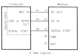
Figure 5 - Pictorial of the Warbler/computer interconnections. Use interconnecting cables that suit your equipment requirements. As shown here, three conductor cables are used at 1 and 2; they are equipped with 3.5-mm stereo connectors at each end. Serial port cable 3 has female DB9 connectors at each end.
Setup
You need software to use the transceiver. If you don't already have it, download and run DigiPan 1.5, the most recent version (see Note 3). Once DigiPan is running, initialize the frequency display to 3582 kHz and select LSB, which places 3582 kHz at the right edge of the display. Connect an antenna and dc power (12 to 15 V) to J5 and J4, respectively. Adjust the sound-card microphone volume-control slider (CONFIGURE | WATERFALL DRIVE in DigiPan 1.5). Set the level with this control to yield blue-to-yellow speckles on the screen. This should yield a band covering approximately one-third of the computer screen width when properly adjusted.
Adjustment
There's only one adjustment on the transceiver board-trimmer cap C3. The ARRL was kind enough to furnish a calibration marker to adjust these rigs. During many of the afternoon and evening hours, W1AW is transmitting on 3581.5 kHz.(7) If you're located east of the Mississippi, you should have little trouble spotting W1AW's CW transmissions on screen. Using a small screwdriver, simply adjust C3 until W1AW's signal is lined up under the 3581.5 tick mark of the DigiPan frequency display. Lacking W1AW's signal, adjust C3 to center the brightest portion of the display screen in the range of 3580.0 to 3581.0 kHz.
If you live close enough to WlAW so that it, signal causes spurious traces on the display, and reducing the sound-card's microphone slide-control setting to cure this eflect causes PSK31 signals to disappear into the noise, try this approach: Set the DigiPan start frequency to 3581.5 kHz and adjust C3 so that W1AW's signal is zero beat at the right extreme of the display. This takes advantage of the low-frequency rolloff characteristics of the receiver's audio amplifier to knock the signal down to manageable levels. Dave, NNIG, lives about two miles from W1AW and its signals are very strong there. Once this adjustment was performed though, Dave could copy PSK31 signals without difficulty.
Transmit adjustment
In DigiPan, select Mode and click on TunE. This places the transceiver in transmit mode with a 100% duty cycle. Click on the speaker icon in Window's tray and advance the volume slider until the transmitter output power is set at 3 W. Although the Warbler's PA stage can be driven harder for more output, the additional power comes at the expense of poorer IMD performance. If you don't have a wattmeter, you can effectively accomplish the job using a 50 Ω resistive load and peak-voltage detector.(8)
Operation
Clicking your computer's mouse cursor over the typical "railroad-track" PSK31 signal should cause text to begin appearing in DigiPan's upper text window. Clicking on T/R in the DigiPan menu switches to transmit and your typed text in the lower window streams out on the air.
Do it, use it, enjoy PSK31!
Just when it seemed to some that the flames of excitement in ham radio were dwindling to smoldering embers, along has come a new mode of communications to stoke us up again. Overwhelming evidence is showing us that folks all over the country are having tons of fun building and operating PSK radio equipment such as the Warbler!
QRPers and high-power operators alike are pulling others into this digital aspect of the hobby by conducting coordinated construction and instruction classes, forming statewide nets on 80 meters for club and special-interest support groups, and plain old ragchewing. There isn't a night that goes by here on the East Coast without having up to a half dozen QSOs going on at once throughout the evening hours.
The fun doesn't stop here! A number of experimenters are using DSP evaluation kits instead of the computer/soundcard approach, so we may see PSK31 terminals that cut the tether to the PC. This will enable an even more portable and lower cost operation for PSK31.
Start enjoying PSK31! Get a local PSK31 ragchew net going in your state. Put on a demo for the local high school science class showing how much fun can be had communicating without using the internet. Get a PSK31 transceiver groupbuild going with your ham club. No matter how you approach it, do it, use it and have fun with PSK31!
Acknowledgements
Thanks to the New Jersey QRP Club, the Western Warbliers and many others I for their enthusiastic support and contributions to this activity.
Notes
- Howard "Skip" Teller, KH6TY, and Dave Benson, NN1G, "A Panoramic Transceiving System for PSK31," QST, Jun 2000, pp 31-37.
- The New Jersey QRP Club offers a complete kit of parts including a PC board, all on-board components and assembly instructions. Price: $45, including shipping in the US and Canada; foreign orders add $5. Make your check or money order payable to George Heron, N2APB. Send your order to George Heron, N2APB, 2419 Feather Mae Ct, Forest Hill, MD 21050. Please allow two to four weeks for delivery. All sales proceeds benefit club-sponsored public activities.
- Warbler project updates and errata are maintained at ???.
- Loaded verticals such as the PM-1 offered by Vernon Wright, W6MMA, is one example of a suitable compact antenna. See also Robert Johns, W3JIP, "A Ground-Coupled Portable Antenna," QST, Jan 2001, pp 28-32.
- John Dillon, WA3RNC, "The Neophyte Receiver," QST, Feb 1988, pp 14-18.
- See the WlAW Operating Schedule in this issue.
- Chuck Hutchinson, K8CH, ed, The ARRL 2001 Handbook (Newington: ARRL, 2000), p 26-11.
NN1G: nn1g@arrl.net