How to maximize your receiver's effective selectivity 2
Minimizing or eliminating noise and interference during reception depends to a great degree on your knowing how to use your receiver's selectivity controls.
In part 1,(1) my discussion focused on using the variable bandwidth tunning (VBT) feature of the Kenwood TS-940S to reduce or eliminate received noise and interference. This month, you'll see how passband tuning, as employed in the Kenwood TS-440S, can help do the same.
Getting the most from IF-shift filters
Let's examine how passband tuning (IF shift) performs when we apply the same philosophy of minimizing signal levels that reach the IF filter. For this graphic analysis, I use the SSB selectivity specifications of the Kenwood TS-440S, which are stated as 2.2 kHz at -6 dB and 4.4 kHz at -60 dB, providing a filter shape factor of 2 in this receiver, compared to a shape factor of 1.5 for the TS-940S. The larger shape-factor number tells you that the selectivity of the TS-440S is somewhat less than that of the TS-940S. With IF passband tuning, you don't have HIGH CUT or LOW CUT controls to reduce the filter bandwidth or to reshape its selectivity curve. You can, however, shift the entire passband of the filter a maximum of ±900 Hz from its center frequency (see Figures 3A trough 3C).
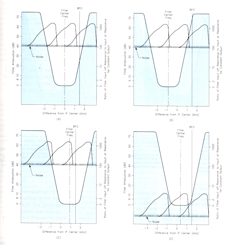
Figure 8-Situation 4, using a TS-440S with passband tuning (IF shift). In each graph, there are two interfering signals, one 2 kHz above another 2 kHz below the desired signal. All three signals are of equal strength, each peaking 25 dB above the noise. At A, the receiver ATTenuator and RF gain controls have not been adjusted to eliminate the interfering signals; the IF SHIFT control is set at zero. The Interfering signals and noise are quite apparent. At B, the only control adjustment made was to set the IF SHIFT control to -900 Hz. As a result, interference from the signal up the band has mostly (not entirely) been eliminated, but interference from the down-band signal and noise is still severe. At C, the IF SHIFT control has been set to +900 Hz, no other control changes have been made. Now, interference from the signal down the band has partially been eliminated, but there's still severe interference from the undesired higher-frequency signal and the noise level is high. A dramatic difference is shown at D. Here, several controls have been used to eliminate the noise and the Interference. The receiver ATTenuator and RF gain controls have been put to work, the IF SHIFT is set at about 360 Hz and the RIT has been adjusted to properly position the BFO In the passband to receive the desired signal.
Situation 4, using a TS-440S, involves two adjacent interfering signals and is illustrated in Figures 8A through 8D. Take a look at Figure 8A. This situation is exactly the same as situation 1 except that the TS-440S employs IF shift instead of VBT. We are trying to receive an LSB signal that peaks 25 dB above the noise. There are two equally strong LSB signals, one 2 kHz above and one 2 kHz below the desired signal. Here (as in Figure 5A for the TS-940S) we assume that with the ATTenuator control of the TS-440S receiver set to 0 dB, and the RF gain control set at maximum, the noise level appears at the 40-dB level at the SSB IF filter in the receiver. In this case, however, we are using a passband-tuning filter with a passband width of about 3.58 kHz at the 40-dB level on the selectivity curve.
By comparing Figure 8A to Figure 5A, you can see that the selectivity curve of the TS-440S is about 0.430 kHz wider at the -40-dB level than that of the TS-940S, and we cannot decrease the bandwidth as we can with the VBT feature of the TS-940S. This means the TS-440S filter will pass more noise at these settings than would the TS-940S VBT filters. As illustrated in Figures 8B and 9C, we could shift the passband of the IF filter up or down in frequency, which would only reduce the interference from one of the two interfering signals while increasing the interference from the other interfering signal. Shifting the passband up or down in frequency makes no change in the amount of noise received.
However, you can still eliminate both interfering signals and the noise. You do this by adjusting the ATTenuator and RF gain controls to slide the signals and noise down the selectivity curve and setting the IF SHIFT control to about +360 Hz as shown in Figure 8D. Here also, you lose some of the desired-signal's higher audio frequencies, but you still have very acceptable communication-quality audio from the desired signal.
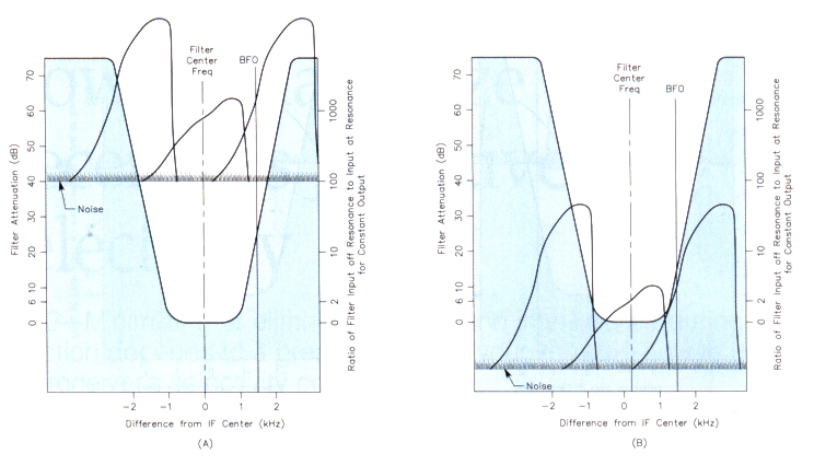
Figure 9 - Situation 5, using a TS-440S with passband tuning (IF shift). Again, there are two Interfering signals, one 2 kHz above and one 2 kHz below the desired signal. The desired signal peaks 25 clB above the noise. Both Interfering signals are 25 dB stronger than the desired signal. At A, the receiver ATTenuator and RF gain controls are wide open and the IF SHIFT is set at zero. As a consequence, the very strong interfering signals blow by the IF filters. None of the lower-intensity interference or noise is eliminated. At B, the input attenuator and RF gain controls have been adjusted to aid in minimizing the interfering signals. The IF SHIFT is set to +211 Hz and the RIT control has been adjusted to properly position the BFO in the passband to receive the desired signal. Although some Interference from the lower-frequency interfering signal remains, Interference from the up-band signal and the noise have been eliminated.
Situation 5 involves two extremely strong adjacent interfering signals and is illustrated in Figures 9A and 9B. What happens when our desired signal is sandwiched between two LSB signals, both 25 dB stronger that our desired signal, one 2 kHz up the band and one 2 kHz down the band and we are using passband tuning? See Figure 9A. Here (as in Figure 6A for the TS-940S) we assume that with the ATTenuator control of the TS-440S set to 0 dB, and the RF gain control set at maximum, the noise level appears at the -40-dB level of the receiver's SSB IF filter. As in Figure 6A, we are trying to receive an LSB signal that peaks 25 dB above the noise. The two interfering signals are strong enough that their peaks will blow by the IF. You simply cannot eliminate much interference from either signal by shifting the IF up or down.
Figure 9B shows that we can slide all three signals and the noise down the selectivity curve to eliminate the noise and adjust the IF shift to eliminate interference from the strong signal up the band, but you can't eliminate all the interference from the strong signal down the band. Can you get rid of this remaining interference? Take a good look at Figure 9B. All of the remaining interference from the LSB signal would be heard as audio that is higher infrequency than that of the portion of the desired signal that has not been eliminated by the IF filter. This is because the RIF components of this interfering signal must beat with BFO to produce audio, and they are farther from the BFO frequency than the unfiltered components of the desired signal. We should be able to use external audio-frequency filtering such as DSP to get rid of these interfering audio frequencies.
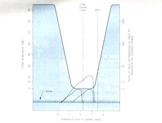
Figure 10 - Situation 6, using a TS-440S with passband tuning (IF shift). The desired signal peaks 25 dB above the noise level. One interfering signal is on the same frequency as the desired signal, another is 1 kHz below the desired signal. Both interfering signals peak 12.5 dB above the noise level. Here, the IF SHIFT control Is at zero, but the receiver ATTenuator and RF gain controls have been adjusted to eliminate the interfering signals and noise.
Figure 10 presents situation 6, which involves interfering signals at the same frequency, or very close to same frequency as that of the desired signal, but somewhat weaker than the desired signal. Looking back at the preceding examples and graphs, you'll see that, in all cases, we have eliminated the noise by using the ATTenuator and the RF gain control to slide the noise below the flat bottom of the selectivity curve. Comparing Figure 10 to Figure 7 you will see that we can use the same approach to eliminate interfering signals that are weaker than the desired signal and on, or very near, the desired signal frequency. A slight adjustment of the IF SHIFT control will also make a slight improvement in the received audio. As we found with the TS-940S, the audio of the on-frequency interfering signal would sound perfectly normal; all components of the off-frequency interfering signal would beat with the BFO, sound I kHz higher than normal and be unintelligible and annoying.
These graphs clearly verify that VBT IF filters are somewhat more effective than IF shift filters, but IF shift filters can often still be used quite effectively to eliminate interference and noise-if you know how to use them effectively.
What's the bottom line?
Take another good look at Figures 5B, 6B, 7, 8D, 9Band 10. What do they all have in common? Simple! These figures all show how interference and noise have been eliminated or at least reduced by using receiver ATTenuator and RF gain controls to slide the desired signal, the interference and the noise to the bottom of the receiver IF-filter selectivity curves. This allows the filters to do their best in eliminating noise and interference. With practice, you'll learn approximately where the receiver front-end controls should be set for optimum receiver performance on each band. Then you can set them as you change bands and almost forget about changing them as you tune a band because you probably won't even hear some of the interference and noise that you have suffered with until now. Keep in mind, however, that changing band conditions may affect your initial control settings.
What does AGC have to do with selectivity?
Refer to Figures 2 and 3. If a strong interfering signal manages to exceed the filters' estimated 75-dB maximum attenuation level, it may blow by them, causing interference to the desired signal and undesired AGC action. If you have the AGC turned off, the AGC will not respond to the strong interfering signal. If your transceiver (such as a TS-440S) has no provision for turning off the AGC, you'll probably get better results by using fast AGC instead of slow AGC.
But my S meter...
Some of you might say: "My S meter doesn't work when I operate the receiver as you describe!" Don't be smercerned. Except for making momentary comparative signal readings in the absence of fading, S-meter readings are virtually meaningless. If you research S-meter circuits and use, you'll soon discover that you might be able to trust your S-meter's calibration on one band, but not over the entire tuning range of your receiver. S-meter calibration varies from receiver to receiver. As a receiver ages, component values may change, affecting S-meter calibration. Antenna location and type, feed-band line loss, impedance mismatches, bandconditions, signal fading and other factors affect S-meter readings. I suggest you forget the S meter. Your primary interest should be minimizing interference.
How does the graphic analysis compare with actual operating experience?
The TS-940S performance shown in Figures 5 through 7 is entirely consistent with the actual performance experienced here at W4QEJ on 75 meters under crowded band conditions when the atmospheric noise level is high. On higher bands, the received noise level is lower and the receiver exhibits less apparent overall front-end internal gain. This is typical of receivers in general. Usually, on the higher HF bands, little or no receiver input attenuation is needed to place signals near or below the filter attenuation curve -6-dB points and more RF gain may be used without causing deterioration of the usable selectivity indicated in the graphs. Pete, W4EHM, who uses a TS-930S, has replaced the original VBT filters with others similar to those in a TS-940S and says his modified TS-930S performs as described.
Warner, W4WAF, and Holt, W4AHA, who both use a TS-440S, say that the performance described reflects their experience when using the receiving techniques presented here. My thanks to W4AHA, W4EHM and W4WAF for the information they provided about their transceivers, and for their comments and advice, all of which were valuable in preparing this article.
Try the approaches I've discussed. I'm sure you, too, will find that they result in interference- and noise-free reception even under crowded band conditions when others are complaining about interference and noise.
W4QEJ