RF impedance matching using ferrite toroidal cores 1
Transmission Line Transformers
Possibly one of the least understood subjects in amateur radio is that of impedance matching. In this series of four articles various methods of impedance matching and transformation using ferrite toroidal cores as a medium will be discussed. There are many applications where impedances must be matched in order to obtain the best interstage energy transfer.
Recently, the writer was faced with the prospect of outlaying in excess of $250 for coaxial cable with which to feed a two element Yagi. Not surprisingly, especially as the antenna was self-designed and constructed in order to save money, the cable was considered rather expensive!
After a few moments reflection, it was recalled how a similar feedline problem had been overcome when a colour television antenna was installed which the salesman had insisted would only operate from coaxial cable. Instead of the "required" coaxial cable, 300 ohm ribbon feeder had been used, attaching it to the antenna terminals marked 300 ohm (it seems strange that they should have these when you can only feed with coaxial cable!).
A store-bought balun was fitted at the television set to match the 300 ohm feeder to the 75 ohm coaxial input to the receiver.
Without doubt, this was the most inexpensive method of feeding the antenna.
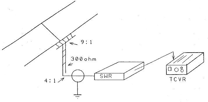
On the home-brew antenna, a split dipole driven element would be used to take a balanced feedline. A balun would be required to match the 35 ohm driven element impedance to the 300 ohm feeder. Another balun would be necessary at the base of the feeder to match into the 75 ohm coaxial cable which contains the SWR/ Power meter and feeds the transceiver. (See fig 1)
It was confidently anticipated that, with only a small amount of judicious adjustment initially to the element lengths, a relatively broadband beam would be achieved with a minimum of fuss and expense.
A pair of baluns, one 9:1 and the other 4:1, would be required.
Firstly, a closer look at these baluns. A balun is a matching device used to couple balanced and unbalanced circuits. In fact they are RF transformers which fit into one of the three following categories:
- Transmission Line Transformers
- Auto-transformers
- Conventional Transformers
1. Transmission line transformers
In its classic balun-form, the transmission line transformer consists of two identical windings, a tap being placed at the centre junction giving a 4:1 impedance transformation from input to output. See Figure 2.
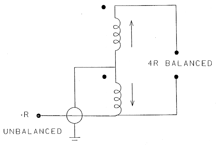
In this specific case, the distinguishing feature of the transmission line transformer is that the winding is composed of two conductors with equal and opposite currents flowing in each, as with conductors in a balanced transmission line. The net magnetising force (ampere-turns) in the core is therefore theoretically nil. As a consequence, ferrite cores with a relatively small cross sectional area can remain unsaturated at relatively high power levels.
In a transmission line transformer the inductance is directly proportional to the permeability of the core material on which the transformer is around. A high permeability material placed close to the transmission line section will act on the external magnetic field thus magnifying the inductance appreciably. There is no influence on intemai magnetic fields or the characteristic impedance of the transmission line. The power being transferred from input to output is not coupled through the ferrite material but rather through the dielectric medium separating the two conductors in the transmission line windings. See Figure 3.
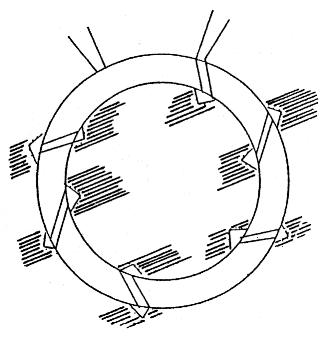
Fig3 - Power Is transferred in the area Immediately about the windings.
A major advantage resulting from the increased inductance provided by the ferrite core is the ability to operate over the range 1 to 30 MHz without having to resort to up to a quarter wavelength of wire for each winding which could be necessary in an air wound transmission line transformer. In practice, six to 10 turns wound onto a ferrite core are usually sufficient to provide the required transmission line simulation.
A true transmission line transformer can only have an impedance ratio equivalent to an integer greater than one squared: 4:1, 9:1 and 16:1 are the most common. To achieve these ratios it is necessary to combine various.4:1 structures on the same or separate cores. See Figure 4.
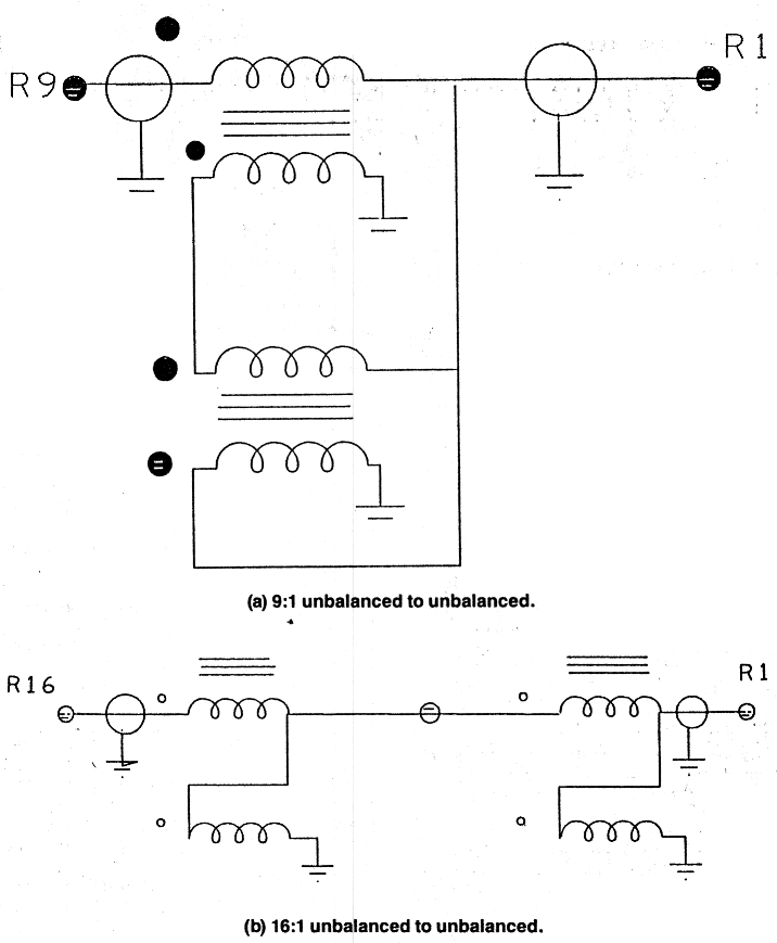
Fig 4
Now back to the task at hand - the two baluns required.
It can be seen from Figure 2 that the transformation from 300 ..ohm balanced twin feeder to 75 ohm unbalanced coaxial cable is covered (4:1) so that it leaves the 9:1 unit.
Unfortunately, the split dipole driven element presents a balanced load and the 300 ohm twin line is also balanced.
Following on from the derivation of the word balun, ie balanced to unbalanced, a balbal would be required (balanced to balanced). Upon checking the usual sources of amateur information, no such word could be found. These devices do exist though as there are several at the writer's shack.
Due to phasing requirements however, a 9:1 balanced to balanced transition is unobtainable in simple transmission line transformers of the type discussed here.
Auto-transformers offer a simple solution to the balanced to balanced requirement and to a wide range of other problems.
This subject will be investigated in Part 2.
Part 1 - Part 2 - Part 3 - Part 4
VK3HK, Stephen Bushell