RF impedance matching using ferrite toroidal cores 3
Conventional transformers
A conventional transformer consists of two separate lengths of wire which are electrically insulated from each other and which form the primary and secondary circuits. When an alternating current is applied to the primary winding, a voltage will be induced in the secondary winding. The intensity of the voltage which is thus induced depends upon the ratio of turns between the windings.
The degree of magnetic coupling between the windings is determined by their proximity to one another and by the permeability of the core about which they are wound. The permeability is, in turn, affected by the degree of current flow and consequent flux density existing in the core. A point will be reached where the core will not pass any greater power. The core is then said to be saturated.
Because of the mode of current transfer just described, the size of the ferrite core when used in a conventional transformer must be larger than for the equivalent current flow in either a transmission line transformer or an auto-transformer.
When a load is connected to the secondary winding, power will be drawn by the primary winding from its current source sufficient to provide for the secondary circuit consumption and any other losses associated with the transformer itself. The impedance of the primary winding is therefore almost exclusively determined by the load connected to the secondary winding and by the turns ratio.
In parts 1 and 2 we realised the benefits and limitations of using transmission line transformers and auto-transformers. The main restriction was the inability to provide a universal current balance format with any required transformation ratio. To meet this requirement it is necessary to have separate primary and secondary windings on our transformer.
The following formula may be used to determine the primary winding impedance (Z):
Z = Zs (Np / Ns)2
Where:
Z = Primary impedance
Zs = Secondary impedance
Np = Primary turns
Ns = Secondary turns
From the above we can derive the following:
Np / Ns = √(Zp / Zs)
Where:
Np / Ns = Primary:secondary turns ratio
Zp = Primary impedance
Zs = Secondary impedance
If we have a primary impedance requirement of 75 ohms and a secondary impedance of 300 ohms then:
Np / Ns = √(Zp / Zs) = √(75 / 300) = √.25 = .5
The primary coil must have half as many turns as the secondary.
Such a transformer is very easily constructed on a toroidal form by using a single trifilar winding which is spread to occupy at least 5/8 of the core circumference. (See Figure 1.).
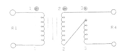
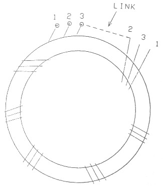
Fig. 1.
Each winding may be identified although I always leave the primary unmarked. The other two are marked according to ones preference. These two secondary windings are then joined bottom to top to provide a series winding which has twice the number of primary turns.
The most important requirement we wished to cover with conventional transformers was current balance format. This is arranged for very easily by simply grounding one side of the winding according to which side of the transformer - primary or secondary, is required to be unbalanced. (See Figure 2.).
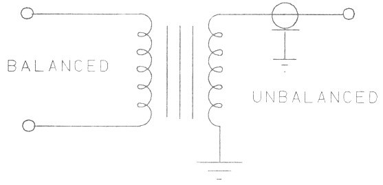
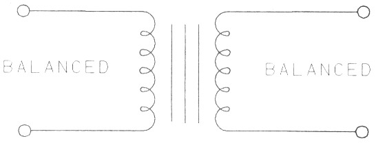
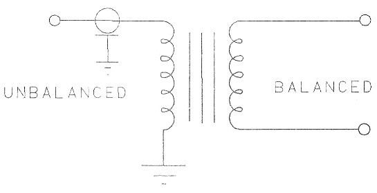
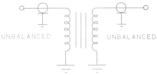
Fig. 2.
Various methods may be employed in constructing the conventional transformer when using ferrite toroidal cores. One method already described used a single multifilar windings. applied to the same core. (See Figure 3.).
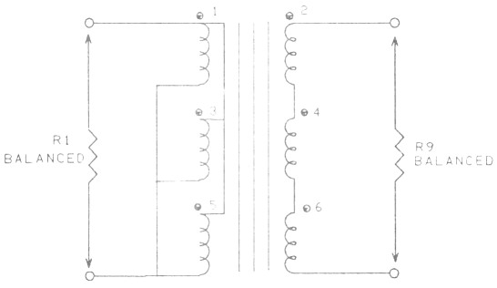
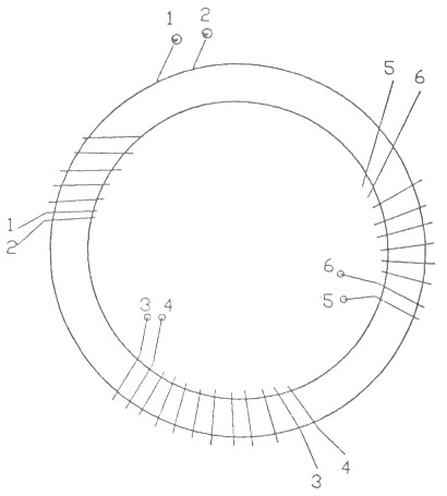
Fig. 3.
Yet another, probably the most conventional method of winding is to simply apply the primary winding to occupy at least 5/8 of the core body and to then wind the secondary over the primary to occupy the same amount of core.
So far we have seen that we can transform most impedance ratios with any current balance by using one of our three transformer families.
Next time we will look at assembly ideas, methods and circuit configurations.
Part 1 - Part 2 - Part 3 - Part 4
VK3HK, Stephen Bushell